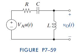
The circuit in Figure P759 is in the zero state when the step function input is applied.
Question:
The circuit in Figure P7–59 is in the zero state when the step function input is applied. The circuit parameters are L ¼
250 mH, C = 1 mF, R ¼ 3.3 kV, and VA ¼ 10 V. Find vO(t) for t 0. (Hint. Find the capacitor voltage first.)
Fantastic news! We've Found the answer you've been seeking!
Step by Step Answer:
Related Book For 

The Analysis And Design Of Linear Circuits
ISBN: 9781118214299
7th Edition
Authors: Roland E Thomas, Albert J Rosa, Gregory J Toussaint
Question Posted:


