Tunable Capacitor In Section 61, Figure 62 (c) shows an air-tunable capacitor as one example of the
Question:
Tunable Capacitor In Section 6–1, Figure 6–2
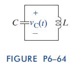
(c) shows an air-tunable capacitor as one example of the capacitor types. This type of device can vary its capacitance similarly to how a potentiometer can vary its resistance. Changing the capacitance in a circuit can change the frequency at which it operates. Suppose we are given the circuit in Figure P6–64 with a capacitor connected in parallel with an inductor. There are no other devices in the circuit. The capacitor has an initial voltage vC(0) ¼ V0 V and the inductor’s initial current is iL(0) ¼ 0 A.
The differential equation for the voltage across the capacitor in this circuit is given by d2vCðtÞ
dt2 þ 1 LC vCðtÞ ¼ 0 We will learn more about solving this type of differential equation in the next chapter and beyond. The solution to this differential equation is vCðtÞ ¼ V0 cos ffitffiffiffiffiffiffi LC p
; t 0 Using MATLAB, plot on a semi-log scale (logarithmic on the horizontal and linear on the vertical,) the radian frequency of vC(t) versus the capacitance of the circuit. Use capacitances scaled logarithmically from 0.001 mF, to 1 mF. In a separate MATLAB figure, use the subplot command to plot vC(t)
versus time for C ¼ 0.001 mF, 0.01 mF, 0.1 mF, and 1 mF. Using the plots you created and your knowledge of how a capacitor stores charge, explain why changing the capacitance of a parallel LC circuit changes the frequency at which is oscillates.
Use MATLAB to solve problem.
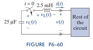
(a) Use the capacitor’s i-v characteristic to find the current i(t) for t 0.
(b) Use the inductor’s i-v characteristic and i(t) to find vL(t)
for t 0.
(c) Use vC(t), vL(t), and KVL to find the voltage v(t) delivered to the rest of the circuit.
(d) The v(t) found in
(c) should be proportional to the i(t)
found in (a). If so, what is the equivalent resistance looking into the rest of the circuit?
(e) On the same axes, plot vC(t), vL(t), and v(t). Use a different color for each waveform. Use the plots to verify KVL for the circuit.
Step by Step Answer:

The Analysis And Design Of Linear Circuits
ISBN: 9781118214299
7th Edition
Authors: Roland E Thomas, Albert J Rosa, Gregory J Toussaint


