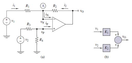
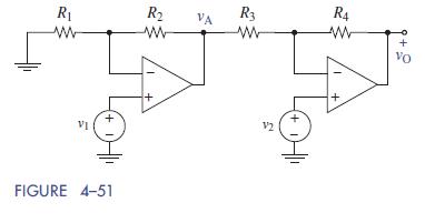
We have looked at two ways to design subtractor circuitsthe more common way as shown in Figure
Question:
We have looked at two ways to design subtractor circuits—the more common way as shown in Figure 4–46 and the less common way as shown in Figure 4–51. Your task is to design OP AMP circuits that meet the following expression: vO = −20v1 +10v2 using both realizations.
At least one resistor in each circuit must be 1 kΩ. The remaining resistors should be selected from the standard 5% values from the inside back cover. Then list pros and cons for each approach.


Fantastic news! We've Found the answer you've been seeking!
Step by Step Answer:
Related Book For 

The Analysis And Design Of Linear Circuits
ISBN: 9781119235385
8th Edition
Authors: Roland E. Thomas, Albert J. Rosa, Gregory J. Toussaint
Question Posted:


