

With the circuit in the zero state, the input to the integrator shown in Figure P1061 is
Question:
With the circuit in the zero state, the input to the integrator shown in Figure P10–61 is v1(t) ¼ cos1000t V.
The desired output is v2(t) ¼ sin 1000t V. Use Laplace to select values of R and C to produce the desired output. If the capacitor had 10 V across it at t ¼ 0, how would that affect the output?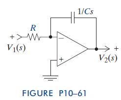
Fantastic news! We've Found the answer you've been seeking!
Step by Step Answer:

Answered By
Lokesh Kumar
EDUCATION-
B.E. (Electronics and Communication Engineering) | Chandigarh College of
Engineering & Technology, Chandigarh
2016 –PRESENT
4.0 GPA (Till 7th Semester)
TECHNICAL SKILLS-
Programming Languages: C, C++,JAVA
Circuit design Softwares: Arduino IDE, Labview,Proteus
PROJECTS-
Human Posture Monitoring System | CCET 2019
Gesture Control Laptop | CCET 2019
0 Reviews
10+ Question Solved
Related Book For 
The Analysis And Design Of Linear Circuits
ISBN: 9781118214299
7th Edition
Authors: Roland E Thomas, Albert J Rosa, Gregory J Toussaint
Question Posted:
