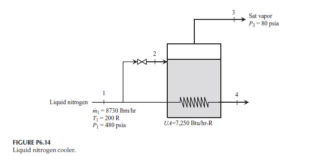
A liquid nitrogen cooler is shown in Figure P6.14. The goal of this system is to cool
Question:
A liquid nitrogen cooler is shown in Figure P6.14. The goal of this system is to cool the liquid nitrogen flow at State 1. This is accomplished by diverting a portion of the liquid through an expansion valve. When the liquid passes through the valve, it flashes into saturated liquid and saturated vapor in the flash tank. The saturated vapor is drawn off the top and the saturated liquid is used to cool the liquid flow using an in-tank heat exchanger. For the conditions shown in Figure P6.14, determine the mass flow rate (lbm/hr) and temperature (°F) of the liquid nitrogen at State 4, and the mass flow rate (lbm/hr) of the saturated vapor at State 3.
Fantastic news! We've Found the answer you've been seeking!
Step by Step Answer:
Related Book For 

Thermal Energy Systems Design And Analysis
ISBN: 9781138735897
2nd Edition
Authors: Steven G. Penoncello
Question Posted:


