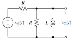
The circuit in Figure (mathrm{P} 7-12) is in the zero state when the input (v_{mathrm{S}}(t)=20 u(t) mathrm{V})
Question:
The circuit in Figure \(\mathrm{P} 7-12\) is in the zero state when the input \(v_{\mathrm{S}}(t)=20 u(t) \mathrm{V}\) is applied. If \(L=150 \mathrm{mH}\) and \(R=\) \(1.0 \mathrm{k} \Omega\), find \(v_{\mathrm{O}}(t)\) for \(t \geq 0\). Identify the forced and natural components in the output. On a single set of axes, use MATLAB to plot the forced response, the natural response, and the complete response.

Fantastic news! We've Found the answer you've been seeking!
Step by Step Answer:
Related Book For 

The Analysis And Design Of Linear Circuits
ISBN: 9781119913023
10th Edition
Authors: Roland E. Thomas, Albert J. Rosa, Gregory J. Toussaint
Question Posted:


