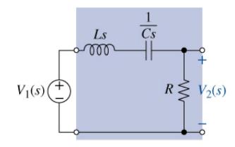
The circuit in Figure P12-32 is a typical (R L C) filter circuit. (a) Find the circuit's
Question:
The circuit in Figure P12-32 is a typical \(R L C\) filter circuit.
(a) Find the circuit's transfer function \(T(s)\) if \(C=33 \mu \mathrm{F}, L=\) \(47 \mathrm{mH}\), and \(R=10 \Omega\).
(b) Determine the filter type.
(c) Use MATLAB to plot the filter's gain characteristic.
(d) Either by hand or from the MATLAB plot, find \(Q, B, \omega_{\mathrm{C} 1}\), \(\omega_{\mathrm{C} 2}, \omega_{\mathrm{o}}\), and \(T_{\text {MAX }}(s)\)
(e) Select a value of \(R, L\), or \(C\) that would shift the center frequency to \(1 \mathrm{krad} / \mathrm{s}\) but not change \(B\).

Fantastic news! We've Found the answer you've been seeking!
Step by Step Answer:
Related Book For 

The Analysis And Design Of Linear Circuits
ISBN: 9781119913023
10th Edition
Authors: Roland E. Thomas, Albert J. Rosa, Gregory J. Toussaint
Question Posted:


