

Question: The feedback circuit in Fig. 9.55 is a switched-capacitor circuit during one clock phase. Assume the op amp is the telescopic-cascode op amp in Fig.
The feedback circuit in Fig. 9.55 is a switched-capacitor circuit during one clock phase.
Assume the op amp is the telescopic-cascode op amp in Fig. 9.54. Take CL= 1.5 pF, CI = 4 pF, CS = 0.4 pF, and Cip = 0.1 pF.
(a) If ITAIL= 0.2 mA, what is the output slew rate?
(b) Assume that gm1= 0.1 mA/V, the loop trans-mission [loop gainT(s) or return ratio R(s)] can be modeled as having two poles, and the magnitude of the nondominant pole p2 is |p2| = 200 Mrad/s.
What is the phase margin of this feedback circuit?
Figure 9.55:
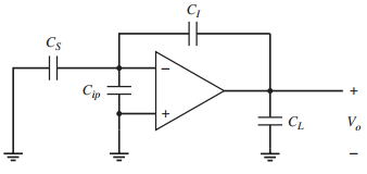
C, Cs Cip V. CL
Step by Step Solution
3.52 Rating (165 Votes )
There are 3 Steps involved in it
a The equivalent load is C L C L C I C S C ip 15 4 04 01 19 pF SR 02m... View full answer

Get step-by-step solutions from verified subject matter experts
Document Format (2 attachments)
1528_605d88e1c4e0a_687065.pdf
180 KBs PDF File
1528_605d88e1c4e0a_687065.docx
120 KBs Word File