

Question: Figure Q25.12 shows two concentric, conducting loops. We will define a counterclockwise current (viewed from above) to be positive, a clockwise current to be negative.
Figure Q25.12 shows two concentric, conducting loops. We will define a counterclockwise current (viewed from above) to be positive, a clockwise current to be negative. The graph shows the current in the outer loop as a function of time. Sketch a graph that shows the induced current in the inner loop. Explain.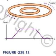
Touter right 1 FIGURE Q25.12
Step by Step Solution
There are 3 Steps involved in it
1 Expert Approved Answer
Step: 1 Unlock

Question Has Been Solved by an Expert!
Get step-by-step solutions from verified subject matter experts
Step: 2 Unlock
Step: 3 Unlock