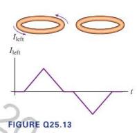
Figure Q25.13 shows conducting loops next to each other. We will define a counterclockwise current (viewed from
Question:
Figure Q25.13 shows conducting loops next to each other. We will define a counterclockwise current (viewed from above) to be positive, a clockwise current to be negative. The graph shows the current in the left loop as a function of time. Sketch a graph that shows the induced current in the right loop. Explain.
Step by Step Answer:
Related Book For 

College Physics A Strategic Approach
ISBN: 9780321907240
3rd Edition
Authors: Randall D. Knight, Brian Jones, Stuart Field
Question Posted:


