

Question: In Figure 9.5, show the process of frame change in routers R1 and R2. Figure 9.5 Figure 7.5 UTP connector 12345678 2343678 RJ-45 Female RJ-45
In Figure 9.5, show the process of frame change in routers R1 and R2.
Figure 9.5
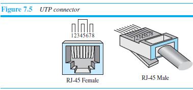
Figure 7.5 UTP connector 12345678 2343678 RJ-45 Female RJ-45 Male
Step by Step Solution
★★★★★
3.41 Rating (164 Votes )
There are 3 Steps involved in it
1 Expert Approved Answer
Step: 1 Unlock

a Router R1 gets the frame received from interface L2 decapsulates the network layer pac... View full answer
Question Has Been Solved by an Expert!
Get step-by-step solutions from verified subject matter experts
Step: 2 Unlock
Step: 3 Unlock