

Question: The following control inputs are active in the bus system shown in Fig. 5-4. For each case, specify the register transfer that will be executed
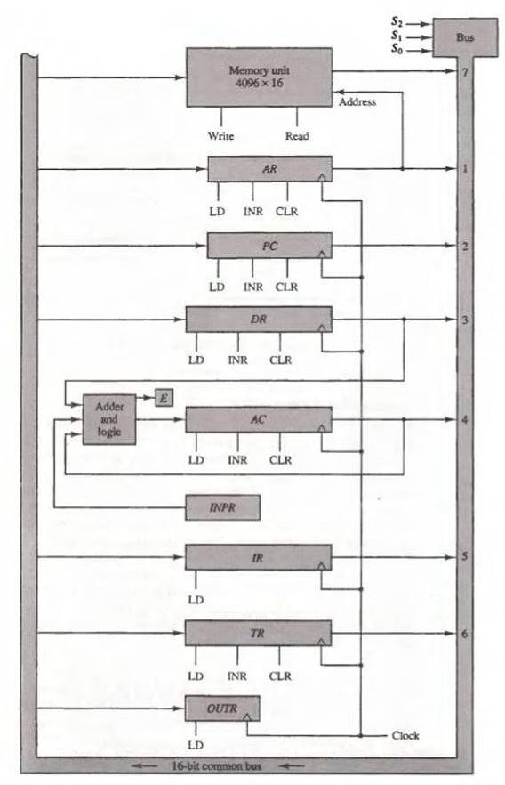
The following control inputs are active in the bus system shown in Fig. 5-4. For each case, specify the register transfer that will be executed during the next clock transition.
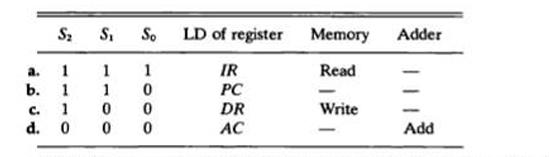
Fig. 5-4
a. b. C. d. S S So 1 1 1 1 1 0 0 0 1000 0 LD of register IR PC DR AC Memory Adder Read Write - Add
Step by Step Solution
★★★★★
3.47 Rating (160 Votes )
There are 3 Steps involved in it
1 Expert Approved Answer
Step: 1 Unlock

Lets examine the provided control inputs and ascertain the action that will be carried out during th... View full answer
Question Has Been Solved by an Expert!
Get step-by-step solutions from verified subject matter experts
Step: 2 Unlock
Step: 3 Unlock