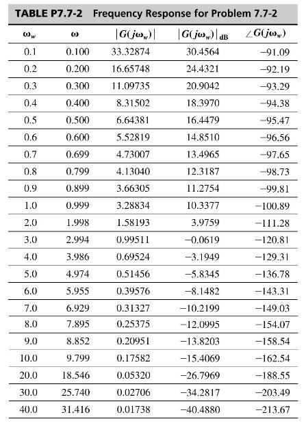
For the antenna control system of Problem 7.5-5 and Fig. P7.5-5, let (K=1). (a) The frequency response
Question:
For the antenna control system of Problem 7.5-5 and Fig. P7.5-5, let \(K=1\).
(a) The frequency response for \(G(z)\) was calculated by computer and is given in Table P7.7-2. Sketch the Nyquist diagram for the open-loop function \(G(z) H_{k}\), with \(H_{k}=0.04 \Rightarrow-7.96 \mathrm{~dB}\).
(b) Determine the stability of the system.
(c) If the system is stable, determine the gain and phase margins. If the system is unstable, find the value of \(K\) that gives a phase margin of \(45^{\circ}\).
(d) From the Nyquist diagram, determine the value of \(K>0\) for which the system is marginally stable.
(e) Find the frequency \(\omega\) at which the marginally stable system will oscillate.

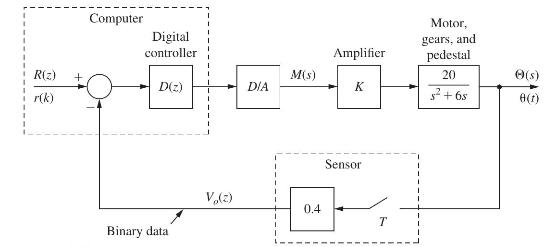
Problem 7.5-5
Consider the antenna control system of Fig. P7.5-5. This system is described in Problem 1.5-1. For this problem, \(T=0.05 \mathrm{~s}\) and \(D(z)=1\). It was shown in Problem 5.3-15 that
\[
y\left[\frac{1-\varepsilon^{-T s}}{s} \frac{20}{s(s+6)}ight]=\frac{0.02268 z+0.02052}{(z-1)(z-0.7408)}
\]
Fig. P7.5-5

Step by Step Answer:

Digital Control System Analysis And Design
ISBN: 9781292061221
4th Global Edition
Authors: Charles Phillips, H. Nagle, Aranya Chakrabortty


