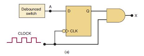
Figure 5-38(a) shows a situation where input signal A is generated from a debounced switch that is
Question:
Figure 5-38(a) shows a situation where input signal A is generated from a debounced switch that is actuated by an operator (a debounced switch was first introduced in Example 5-2). A goes HIGH when the operator actuates the switch and goes LOW when the operator releases the switch. This A input is used to control the passage of the clock signal through the AND gate so that clock pulses appear at output X only as long as A is HIGH.
The problem with this circuit is that A is asynchronous; it can change states at any time relative to the clock signal because the exact times when the operator actuates or releases the switch are essentially random. This can produce partial clock pulses at output X if either transition of A occurs while the clock signal is HIGH, as shown in the waveforms of Figure 5-38(b).
This type of output is often not acceptable, so a method for preventing the appearance of partial pulses at X must be developed. One solution is shown in Figure 5-39(a). Describe how this circuit solves the problem, and draw the X waveform for the same situation as in Figure 5-38(b).
Figure 5-38
 Figure 5-39(a)

Step by Step Answer:

Digital Systems Principles And Application
ISBN: 9780134220130
12th Edition
Authors: Ronald Tocci, Neal Widmer, Gregory Moss


