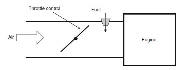
Question: The conceptual sketch below shows a model for a closed loop control of a lawnmower engine. Unlike the lawn mower motor of exercise 7, there
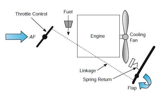
The conceptual sketch below shows a model for a closed loop control of a lawnmower engine. Unlike the lawn mower motor of exercise 7, there is a feedback device. It takes advantage of a cooling fan that is connected directly to the output shaft of the lawn mower. This fan blows on a flap indicated in the diagram, which is preset to a desired position and kept in that position against a spring tension if the fan is rotating at a desired speed. The desired speed is set by initializing the spring with a tension SSP corresponding to a desired operating condition such as 3,000 RPM.

If the fan rotates too fast (i.e., the engine speed is too high), the flap is blown clockwise, causing a mechanical linkage to close the throttle and reduce engine speed. If the speed is too low, the flap is pulled counterclockwise by the spring. Draw a block diagram for this control system, assuming:
(1) That the control unit sends an error signal in terms of the spring tension (SSP (set point) – S) to throttle a proportional amount of air/fuel GTh(SSP – S) kg/s;
(2) Resulting in engine power P = GE × AF;
(3) The speed response function for the motor speed is N = GSR × P. Finally the controller converts engine speed to spring tension by the relationship S = GSTN.
Exercise 7

Fuel Throttle Control Cooling Fan AF Engine Linkage Spring Return Flap
Step by Step Solution
3.51 Rating (158 Votes )
There are 3 Steps involved in it
SSP Error Control Throttle Engine Engine Signal Unit Power Speed GThSSP S P GE AF N GSR P Throttle C... View full answer

Get step-by-step solutions from verified subject matter experts


