

Question: A synchronous sequential circuit is represented by the state diagram shown in Figure P5.17. Using JK flip-flops and undefined states as dont cares: (a) Derive
A synchronous sequential circuit is represented by the state diagram shown in Figure P5.17. Using JK flip-flops and undefined states as don’t cares:
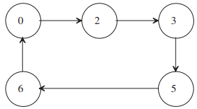
(a) Derive the state table.
(b) Minimize the equation for flip-flop inputs using K-maps.
(c) Draw a logic diagram.
2
Step by Step Solution
★★★★★
3.40 Rating (169 Votes )
There are 3 Steps involved in it
1 Expert Approved Answer
Step: 1 Unlock

a Drive state table b Minimize using Kmaps c Log... View full answer
Question Has Been Solved by an Expert!
Get step-by-step solutions from verified subject matter experts
Step: 2 Unlock
Step: 3 Unlock