

Question: help for all questions Ch5: Sequential Circuits A- Latches and Flip-Flops 1- Latches are A. Edge sensitive. B. Both edge and level sensitive. C. Level

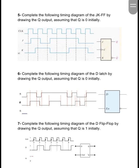
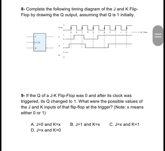
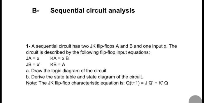
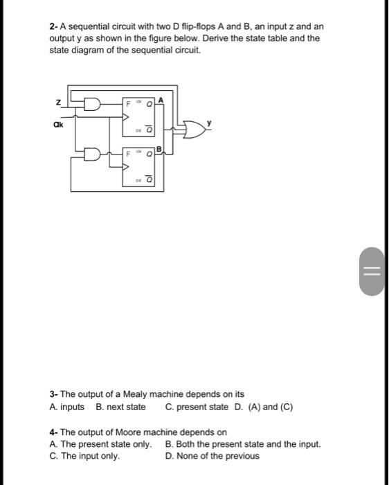
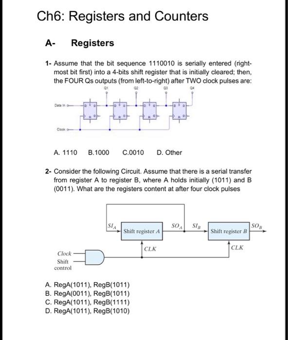
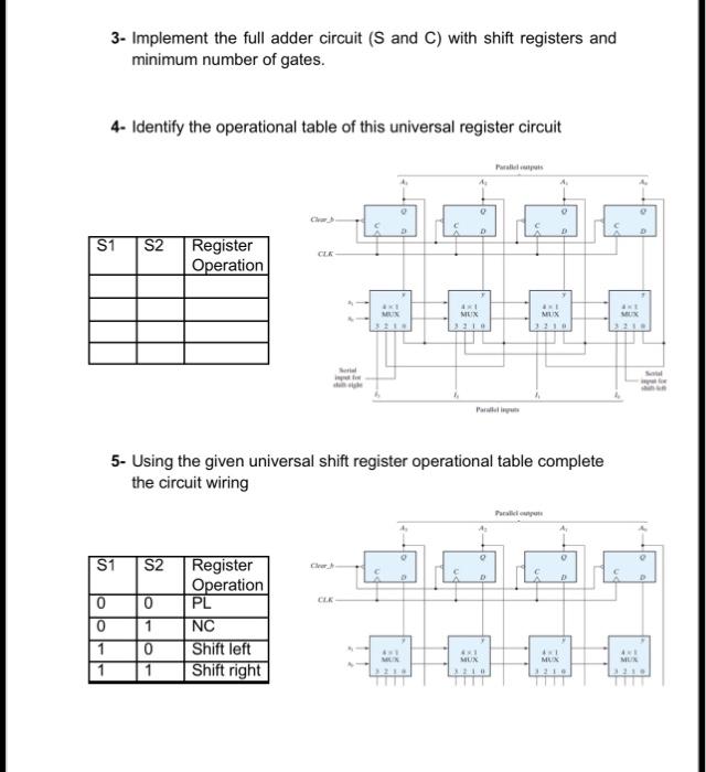
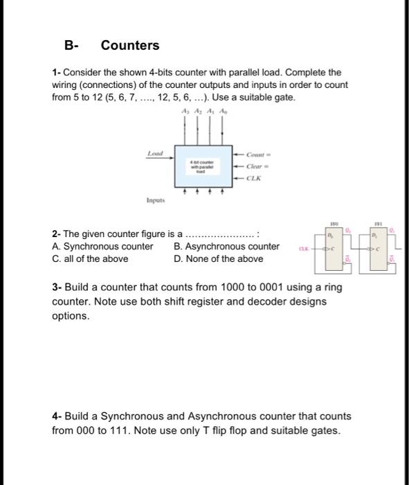
Ch5: Sequential Circuits A- Latches and Flip-Flops 1- Latches are A. Edge sensitive. B. Both edge and level sensitive. C. Level sensitive. D. None of the previous 2- Flip-Flops are A. Edge sensitive. B. Both edge and level sensitive. C. Level sensitive. D. None of the previous 3- Which of the following represent the asynchronous inputs of the shown D Flip-Flop: A. CLK B. D C. Q D.CLR 4- The circuit shown in the Figure is a: A. 3-bit Synchronous Binary Counter B. 4-bit Asynchronous Binary Counter C. 4-bit shift register D. None of the above 5- Complete the following timing diagram of the JK-FF by drawing the Q output, assuming that Q is 0 initially. 6- Complete the following timing diagram of the D latch by drawing the Q output, assuming that Q is 0 initially. 7- Complete the following timing diagram of the D Flip-Flop by drawing the Q output, assuming that Q is 1 initially. 8- Complete the following timing diagram of the J and K FlipFlop by drawing the Q output, assuming that Q is 1 initially. 9- If the Q of a J-K Flip-Flop was 0 and after its clock was triggered, its Q changed to 1 . What were the possible values of the J and K inputs of that flip-flop at the trigger? (Note: x means either 0 or 1 ) A. J=0 and K=x B. J=1 and K=x C. J=x and K=1 D. J=x and K=0 B- Sequential circuit analysis 1- A sequential circuit has two JK flip-flops A and B and one input x. The circuit is described by the following flip-flop input equations: JA=xJB=x,KA=xBKB=A a. Draw the logic diagram of the circuit. b. Derive the state table and state diagram of the circuit. Note: The JK flip-flop characteristic equation is: Q(t+1)=JQ+KQ 2- A sequential circuit with two D flip-flops A and B, an input z and an output y as shown in the figure below. Derive the state table and the state diagram of the sequential circuit. 3- The output of a Mealy machine depends on its A. inputs B. next state C. present state D. (A) and (C) 4- The output of Moore machine depends on A. The present state only. B. Both the present state and the input. C. The input only. D. None of the previous Ch6: Registers and Counters A- Registers 1- Assume that the bit sequence 1110010 is serially entered (rightmost bit first) into a 4-bits shift register that is initially cleared; then, the FOUR Qs outputs (from left-to-right) after TWO clock pulses are: A. 1110 B. 1000 C.0010 D. Other 2- Consider the following Circuit. Assume that there is a serial transfer from register A to register B, where A holds initially (1011) and B (0011). What are the registers content at after four clock pulses A. RegA(1011),RegB(1011) B. RegA(0011),RegB(1011) C. RegA(1011),RegB(1111) D. RegA(1011),RegB(1010) 3- Implement the full adder circuit (S and C ) with shift registers and minimum number of gates. 4- Identify the operational table of this universal register circuit 5- Using the given universal shift register operational table complete the circuit wiring 1- Consider the shown 4-bits counter with parallel load. Complete the wiring (connections) of the counter outputs and inputs in order to count from 5 to 12(5,6,7,.,12,5,6,). Use a suitable gate. 2- The given counter figure is a A. Synchronous counter B. Asynchronous counter C. all of the above D. None of the above 3- Build a counter that counts from 1000 to 0001 using a ring counter. Note use both shift register and decoder designs options. 4- Build a Synchronous and Asynchronous counter that counts from 000 to 111. Note use only T flip flop and suitable gates
Step by Step Solution
There are 3 Steps involved in it

Get step-by-step solutions from verified subject matter experts