

Question: Write Verilog code for the divider circuit that has the data path in Figure 7.30 and the control circuit represented by the ASM chart in
Write Verilog code for the divider circuit that has the data path in Figure 7.30 and the control circuit represented by the ASM chart in Figure 7.31.
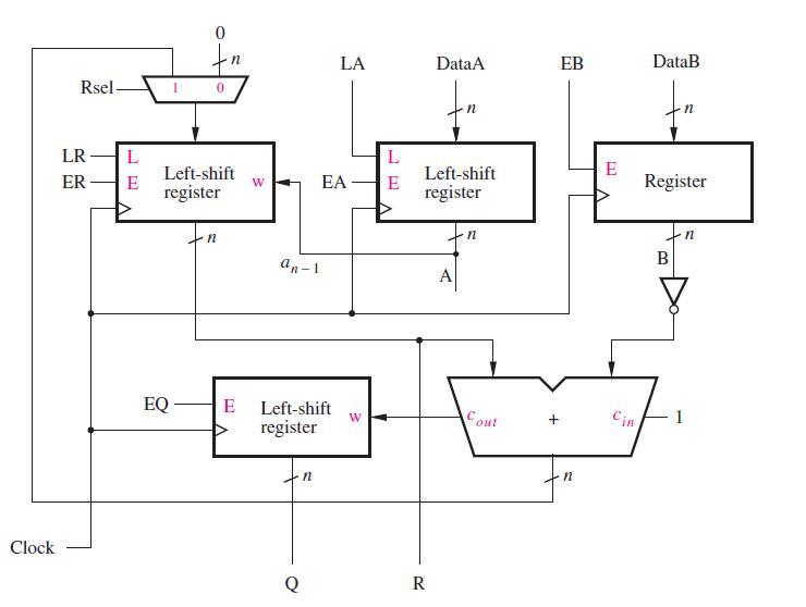
Clock Rsel- LR L ER E 0 EQ 0 Left-shift register n n E W an-1 Left-shift register n LA L EA E W DataA Left-shift register R A Cout EB n E [1] Cin DataB Register B n
Step by Step Solution
★★★★★
3.37 Rating (172 Votes )
There are 3 Steps involved in it
1 Expert Approved Answer
Step: 1 Unlock

To provide a detailed answer for the divider circuit us... View full answer
Question Has Been Solved by an Expert!
Get step-by-step solutions from verified subject matter experts
Step: 2 Unlock
Step: 3 Unlock