

Question: Write Verilog code for the boundary scan cell of Figure 10-14(b). Rewrite the Verilog code of Figure 10-21 to use this boundary scan cell as
Write Verilog code for the boundary scan cell of Figure 10-14(b). Rewrite the Verilog code of Figure 10-21 to use this boundary scan cell as a component in place of some of the behavioral code for the BSR. Use a generate statement to instantiate NCELLS copies of this component. Test your new code using the boundary scan tester example of Figure 10-22.
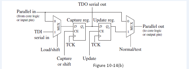
TDO serial out Parallel in (from core logic or input pin) Capture reg. Update reg. -Parallel out (to core logic or output pin) D Q, CE D Q, CE TDI- serial in TCK TCK Normal/test Load/shift Update Figure 10-14(b) Capture or shift
Step by Step Solution
3.48 Rating (171 Votes )
There are 3 Steps involved in it
Verilog code for Figure 1014 b is as follows module BSCell TDI BSRin SLmode TNmod... View full answer

Get step-by-step solutions from verified subject matter experts