

Question: Write Verilog code that represents the circuit in Figure 11.12. W V Y Resetn Q D 10 o Scan-out 10 D V Clock Y Y
Write Verilog code that represents the circuit in Figure 11.12.
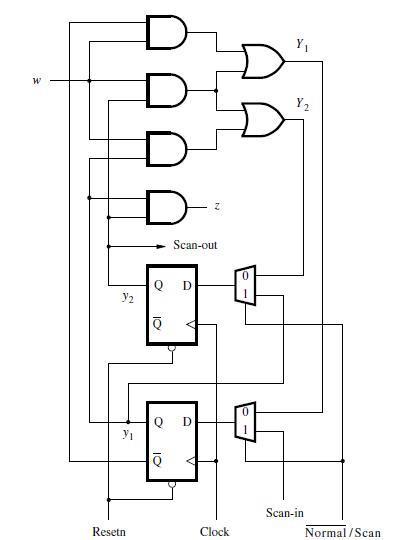
W V Y Resetn Q D 10 o Scan-out 10 D V Clock Y Y Scan-in Normal/Scan
Step by Step Solution
★★★★★
3.41 Rating (167 Votes )
There are 3 Steps involved in it
1 Expert Approved Answer
Step: 1 Unlock

module multiplier input wire clk input w... View full answer
Question Has Been Solved by an Expert!
Get step-by-step solutions from verified subject matter experts
Step: 2 Unlock
Step: 3 Unlock