

Question: Part V Figure 7 : A circuit that can select and display one of three characters. After completing simulations of your code, make a Quartus
Part V Figure : A circuit that can select and display one of three characters.
After completing simulations of your code, make a Quartus project for this part of the exercise.
Include the required pin assignments for the DESoC board for all switches, LEDs, and segment displays.
Compile the project.
Download the compiled circuit into the FPGA chip. Test the functionality of the circuit by setting the proper
character codes on the switches and then toggling to observe the rotation of the characters.
module figSW LEDR, HEX;
input : SW; toggle switches
output : LEDR; red LEDs
output : HEx; seg displays
assign LEDR SW;
declare any wires needed
code not shown
instantiate module muxbittol S U V W M;
muxbittol M;
instantiate module charseg C Display;
charseg H;
endmodule
implements a bit wide to multiplexer
module muxbittoS U V W M;
input : S U V W;
output : M;
code not shown
endmodule
implements a segment decoder for d E I and 'blank'
module charseg C Display;
input : C; input code
output : Display; output seg code
code not shown
endmodule
Figure : Verilog code for the circuit in Figure Table Rotating the word dE on three displays.
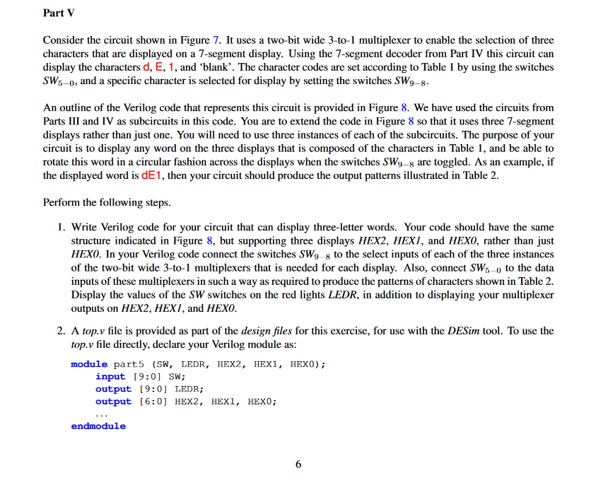
Consider the circuit shown in Figure It uses a twobit wide to multiplexer to enable the selection of three
characters that are displayed on a segment display. Using the segment decoder from Part IV this circuit can
display the characters and 'blank'. The character codes are set according to Table by using the switches
and a specific character is selected for display by setting the switches
An outline of the Verilog code that represents this circuit is provided in Figure We have used the circuits from
Parts III and IV as subcircuits in this code. You are to extend the code in Figure so that it uses three segment
displays rather than just one. You will need to use three instances of each of the subcircuits. The purpose of your
circuit is to display any word on the three displays that is composed of the characters in Table and be able to
rotate this word in a circular fashion across the displays when the switches are toggled. As an example, if
the displayed word is dE then your circuit should produce the output patterns illustrated in Table
Perform the following steps.
Write Verilog code for your circuit that can display threeletter words. Your code should have the same
structure indicated in Figure but supporting three displays HEX HEX and HEXO, rather than just
HEXO. In your Verilog code connect the switches to the select inputs of each of the three instances
of the twobit wide to multiplexers that is needed for each display. Also, connect to the data
inputs of these multiplexers in such a way as required to produce the patterns of characters shown in Table
Display the values of the switches on the red lights LEDR, in addition to displaying your multiplexer
outputs on HEX HEXI, and HEXO.
A top.v file is provided as part of the design files for this exercise, for use with the DESim tool. To use the
top. file directly, declare your Verilog module as:
module partSW LEDR, HEX HEX HEX;
input : SW;
output : LEDR;
output : HEX HEX HEX;
endmodule
Step by Step Solution
There are 3 Steps involved in it
1 Expert Approved Answer
Step: 1 Unlock

Question Has Been Solved by an Expert!
Get step-by-step solutions from verified subject matter experts
Step: 2 Unlock
Step: 3 Unlock