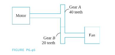
A schematic of part of a power transmission system is shown in Figure P6.46. A motor of
Question:
A schematic of part of a power transmission system is shown in Figure P6.46. A motor of moment of inertia \(I=100 \mathrm{~kg} \cdot \mathrm{m}^{2}\) is mounted on a shaft of shear modulus \(G=80 \times 10^{9} \mathrm{~N} / \mathrm{m}^{2}\), polar moment of inertia \(J=2.3 \times 10^{-4} \mathrm{~m}^{4}\), and length \(10 \mathrm{~cm}\). Gear A, of moment of inertia \(50 \mathrm{~kg} \cdot \mathrm{m}^{2}\) with 40 teeth is at the end of the shaft which meshes with a gear, gear \(B\), of moment of inertia \(25 \mathrm{~kg} \cdot \mathrm{m}^{2}\) with 20 teeth. Gear B is on a shaft of elastic modulus \(G=80 \times\) \(10^{9} \mathrm{~N} / \mathrm{m}^{2}\), polar moment of inertia \(J=1.2 \times 10^{-5} \mathrm{~m}^{4}\), and length \(60 \mathrm{~cm}\). At the end of the shaft is a large industrial fan of moment of inertia \(300 \mathrm{~kg} \cdot \mathrm{m}^{2}\). Determine the natural frequencies of the system and the modal fractions.

Step by Step Answer:


