Your lab write-up should include your schematics, screenshots of your LTSPICE analysis, a discussion of your results, and a conclusion. Part A: Reflections on a
Your lab write-up should include your schematics, screenshots of your LTSPICE analysis, a discussion of your results, and a conclusion.
Part A: Reflections on a Transmission Line
Objective: To observe the effect of reflections on a transmission line
Figure 1 shows a basic test setup that can be used for observing the performance of coaxial cable transmission lines.

Figure 1: Test Setup
The transmission line model available on LTSPICE is useful, but it has its limitations. The component is called line and can be found in the same Components menu where you find voltage sources, transistors, and so on. The component looks like this:
Figure 2: LTSPICE Tline Component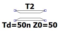
The nodes at the upper left and upper right are the center conductor at either end of the cable. The nodes at the lower left and lower right are the shield at either end of the cable. The transmission line model only has two parameters: the propagation delay Td and the characteristic impedance Z0. To make changes to these values, right-click on the component to open the Attribute Editor. If you click in the Value area, you can make changes to either or both of these parameters.
1) If you were building this circuit in the lab, you would use a BNC T-connector with RG-58 coaxial cable. Figure 3 below shows a male connection on the left, and a female connection on the right.
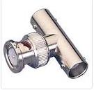
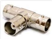
Figure 3: BNC T-connectors
The female connector would be attached to your function generator. For this lab, you would use a short BNC to BNC cable (1 foot) to connect the function generator to the oscilloscope. You would connect a long coaxial cable (40 feet) to the other end of the T connector. Use the specifications for RG-58 coaxial cable to determine the parameters to use in your LTSPICE simulation for each cable.
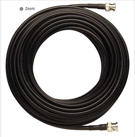
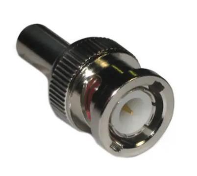
Figure 4: RG-58 Coaxial Cable and BNC Male Connector
Your input voltage will be a 0 to 5V square wave at 1 MHz. If you were doing this in the lab, you would put the waveform generator into its 50Ω output mode. To simulate this on LTSPICE, you will create a 10V voltage source with a series 50Ω output resistance (the 50Ω output resistance would be internal to the waveform generator). This would create a voltage divider with a 50Ω load, so the resulting output would be 5V. The rise time and fall time should be very fast in comparison to the squarewave period (0.5 sec is reasonable).
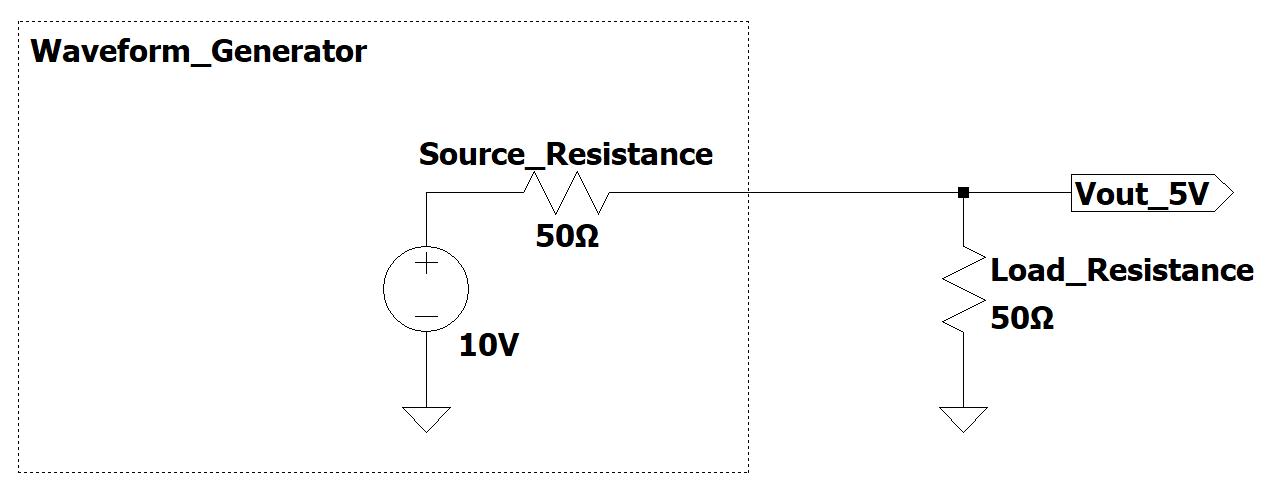
Figure 5: Waveform Generator Output
2) Using the specifications for RG-58 cable, find the characteristic impedance of the cable and the propagation time for the short and long cables. Enter these values into your LTspice tline components for the short and long cables.
Connect a resistor, as close in value to the characteristic impedance as possible, to the end of the long cable. Connect the short cable to a resistor simulating the input resistance of an oscilloscope (1MΩ is reasonable). Be careful to ground the cables’ shielding at both ends.
3) Observe the outputs from the end of the short cable and the end of the long cable. You should see a 0 – 5 V square wave on both channels with the output waveform lagging the input by an amount determined by the length of the cable. Measure and record the time difference between the leading edges.
4) The edges on your signals may not look like perfect squarewaves, although the voltage source is sending out a perfect squarewave. What causes this difference?
5) Remove the resistor from the end of the long cable and observe both waveforms again. This time you should see that both signals have doubled in size. However, it takes twice the travel time at the source end for this to happen because now there is a reflected wave that has to travel back to the source end. You will see the same time difference between leading edges of the two waveforms, but the source end will double in size when the reflection reaches the source.
6) Verify that you see the effect of the reflected wave at the source end and measure the two way travel time by observing the short cable output and measuring the time from the beginning of the first plateau to when it fully reaches its maximum value
7) Repeat the last observation, this time with the load end shorted instead of open. Both waveforms should be at zero volts except that a short pulse appears on the source end of the cable. Re-measure the two-way travel time by measuring the length of the pulse.
Part B: Simulating a TDR
Objective: To simulate the operation of a TDR
A time domain reflectometer (TDR) is a very useful tool that can be used to investigate the properties of a
transmission line over a long distance. With a TDR, you look at the signal at the near end of a transmission line to draw conclusions about the situation at the far end of the line.
1) Connect a 100 resistor to the end of the long cable and observe the waveform at the end of the short cable. Explain why the waveform looks the way it does.
2) Replace the 100 resistors with a 25-load resistor and observe the waveform at the end of the short cable. Explain why the waveform looks the way it does.
Part C: SWR Measurements
Objective: To investigate standing waves and electrical length on a transmission line
With an AC input into a resonant transmission line (that is, a transmission line that is terminated with a resistance different from its characteristic impedance), standing waves can form along the line.
1) Change the function generator to produce a sine function at 5 V p-p and 1 kHz going to the transmission line. Connect the generator to the long transmission line, but for this part of the experiment disconnect the short cable. Your simplified circuit will look like this:

Figure 6: SWR Test Circuit
2) While viewing the waveform at the source end of the line, connect a 50-load resistor to the other end of the long cable. Adjust your transient analysis parameters so that at least one period of the input waveform is visible. Record the peak-to-peak source-end voltage. Compare the source-end voltage to the load end of the transmission line. Are there any differences? Why or why not?
3) Change the value of the termination resistor to 100. Record the peak-to-peak source-end voltage
4) Calculate the electrical length of the transmission line at this frequency. Note that the line is electrically short at this frequency so the impedance at the source end of the cable is the load resistance value of 100 .
5) Increase the function generator frequency by 1MHz steps to 20MHz while observing any changes in the source-end voltage. You could do this by increasing the frequency in the transient analysis for each step, or you could use an AC analysis.
6) Repeat both the previous steps with a load resistance of 10 .
7) For each of the load resistors, calculate the electrical length of the transmission line at the frequency where you first noticed a 10% change in voltage. This may be different in each of the two load conditions. This is the frequency where we consider this line electrically long and transmission line theory becomes important to consider.
Waveform Generator Short Cable T-Connector Oscilloscope Long Cable Load Resistor
Step by Step Solution
3.38 Rating (157 Votes )
There are 3 Steps involved in it
Step: 1

See step-by-step solutions with expert insights and AI powered tools for academic success
Step: 2

Step: 3

Ace Your Homework with AI
Get the answers you need in no time with our AI-driven, step-by-step assistance
Get Started


