Question
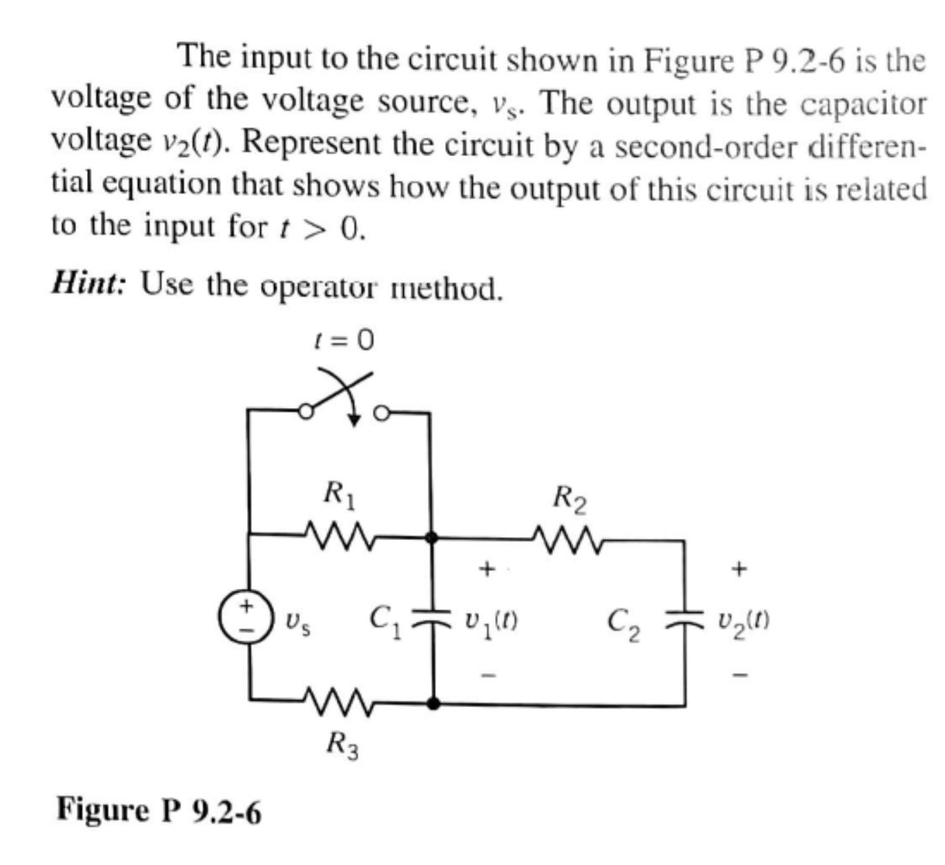
The input to the circuit shown in Figure P 9.2-6 is the voltage of the voltage source, vs. The output is the capacitor voltage

The input to the circuit shown in Figure P 9.2-6 is the voltage of the voltage source, vs. The output is the capacitor voltage v(t). Represent the circuit by a second-order differen- tial equation that shows how the output of this circuit is related to the input for t > 0. Hint: Use the operator method. 1=0 Figure P 9.2-6 Us R C = 0 (1) ww R3 R2 C + 0 (1)
Step by Step Solution
3.40 Rating (159 Votes )
There are 3 Steps involved in it
Step: 1

Get Instant Access to Expert-Tailored Solutions
See step-by-step solutions with expert insights and AI powered tools for academic success
Step: 2

Step: 3

Ace Your Homework with AI
Get the answers you need in no time with our AI-driven, step-by-step assistance
Get StartedRecommended Textbook for
Signals and Systems using MATLAB
Authors: Luis Chaparro
2nd edition
123948126, 978-0123948120
Students also viewed these Electrical Engineering questions
Question
Answered: 1 week ago
Question
Answered: 1 week ago
Question
Answered: 1 week ago
Question
Answered: 1 week ago
Question
Answered: 1 week ago
Question
Answered: 1 week ago
Question
Answered: 1 week ago
Question
Answered: 1 week ago
Question
Answered: 1 week ago
Question
Answered: 1 week ago
Question
Answered: 1 week ago
Question
Answered: 1 week ago
Question
Answered: 1 week ago
Question
Answered: 1 week ago
Question
Answered: 1 week ago
Question
Answered: 1 week ago
Question
Answered: 1 week ago
Question
Answered: 1 week ago
Question
Answered: 1 week ago
Question
Answered: 1 week ago
View Answer in SolutionInn App


