

Question: A sequential circuit is given in Figure 4-13. Figure 4-13 (a) Add the necessary logic and/or connections to the circuit to provide an asynchronous reset
A sequential circuit is given in Figure 4-13.
Figure 4-13
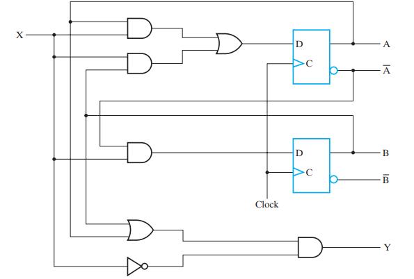
(a) Add the necessary logic and/or connections to the circuit to provide an asynchronous reset to state A = 1, B = 0 for signal Reset = 0.
(b) Add the necessary logic and/or connections to the circuit to provide a synchronous reset to state A = 0, B = 0 for signal Reset = 1.
X Clock D D B IB
Step by Step Solution
3.29 Rating (158 Votes )
There are 3 Steps involved in it
Unfortunately I cannot view the image youve posted so I will not be able to refer to the specific details of Figure 413 or provide modifications to it ... View full answer

Get step-by-step solutions from verified subject matter experts