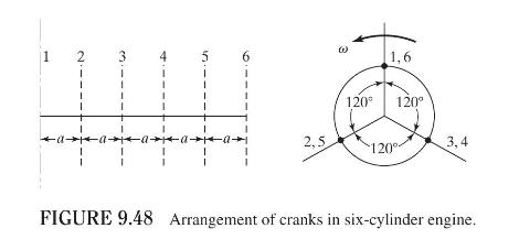
The arrangement of cranks in a six-cylinder in-line engine is shown in Fig. 9.48. The cylinders are
Question:
The arrangement of cranks in a six-cylinder in-line engine is shown in Fig. 9.48. The cylinders are separated by a distance \(a\) in the axial direction, and the angular positions of the cranks are given by \(\alpha_{1}=\alpha_{6}=0^{\circ}, \alpha_{2}=\alpha_{5}=120^{\circ}\), and \(\alpha_{3}=\alpha_{4}=240^{\circ}\). If the crank length, connecting-rod length, and the reciprocating mass of each cylinder are \(r, l\), and \(m\), respectively, find the primary and secondary unbalanced forces and moments with respect to the reference plane indicated in Fig. 9.48.

Fantastic news! We've Found the answer you've been seeking!
Step by Step Answer:
Related Book For 

Question Posted:


