

Question: 1. The permanent magnet dc motor is depicted diagrammatically in Fig. 1, in which the input voltage e, is applied to the armature circuit.
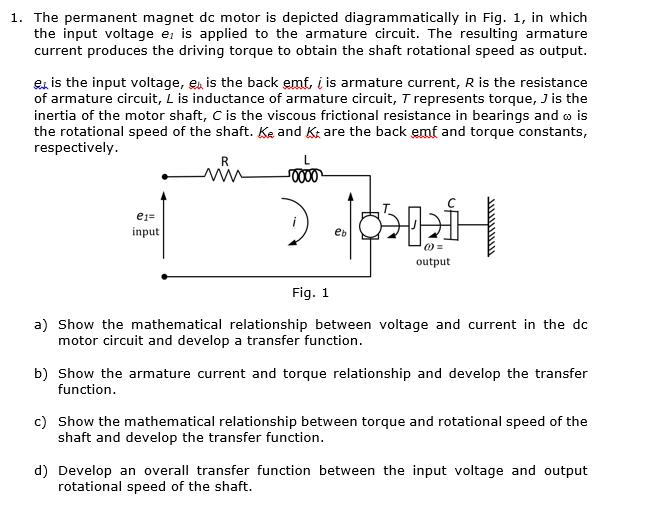
1. The permanent magnet dc motor is depicted diagrammatically in Fig. 1, in which the input voltage e, is applied to the armature circuit. The resulting armature current produces the driving torque to obtain the shaft rotational speed as output. 00 is the input voltage, e is the back emf, iis armature current, R is the resistance of armature circuit, L is inductance of armature circuit, T represents torque, J is the inertia of the motor shaft, C is the viscous frictional resistance in bearings and o is the rotational speed of the shaft. Ke and Kt are the back emf and torque constants, respectively. e1= input R 0000 2 > @= output Fig. 1 a) Show the mathematical relationship between voltage and current in the dc motor circuit and develop a transfer function. b) Show the armature current and torque relationship and develop the transfer function. c) Show the mathematical relationship between torque and rotational speed of the shaft and develop the transfer function. d) Develop an overall transfer function between the input voltage and output rotational speed of the shaft.
Step by Step Solution
There are 3 Steps involved in it
a Relationship between Voltage and Current in the DC Motor Circuit and Transfer Function The voltage equation for the armature circuit of the DC motor can be derived using Kirchhoffs voltage law Accor... View full answer

Get step-by-step solutions from verified subject matter experts