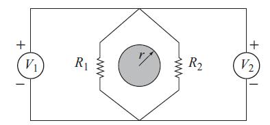
The diagram below shows a planar circuit composed of zero resistance wires, two resistors R 1 and
Question:
The diagram below shows a planar circuit composed of zero resistance wires, two resistors R1 and R2, and two voltmeters V1 and V2. A tightly wound solenoid with radius r produces a magnetic field inside itself that points into the paper with a time increasing magnitude B(t). The voltmeters display the value of the line integral of E along an integration path that passes through the meter from its plus (+) terminal to its minus (−) terminal. What voltage is displayed by voltmeter V1?What voltage is displayed by voltmeter V2? Assume that each voltmeter draws negligible current.

Fantastic news! We've Found the answer you've been seeking!
Step by Step Answer:
Related Book For 

Question Posted:


