

Question: As an approximation to the integrate-and-dump detector in Figure 9.3(a), we replace the integrator with a low pass RC filter with frequency response function where
As an approximation to the integrate-and-dump detector in Figure 9.3(a), we replace the integrator with a low pass RC filter with frequency response function 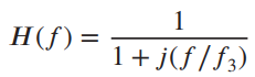
where f3 is the 3-dB cut off frequency
Figure 9.3(a)
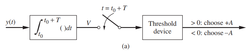
(a) Find s02, (T) / E{n20(t)}, where s0(T) is the value of the output signal at t = T due to +A being applied at t = 0, and n0 (t) is the output noise. (Assume that the filter initial conditions are zero.)
(b) Find the relationship between T and f3 such that the signal-to-noise ratio found in part (a) is maximized. (Numerical solution required.)
H(f) = 1+ j(f/f3) t = to + T to + T ()dt () Threshold device > 0: choose +A < 0: choose A (a)
Step by Step Solution
3.35 Rating (164 Votes )
There are 3 Steps involved in it
a The impulse response of the filter is h t 2f 3 e 2f 3 t u t and th... View full answer

Get step-by-step solutions from verified subject matter experts