please answer me my all simulation lab questions and thank u

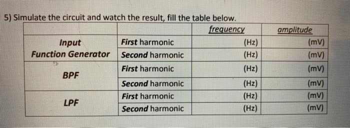
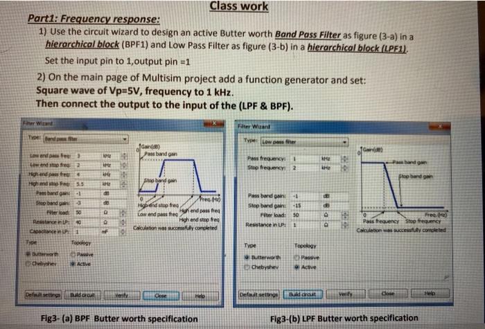
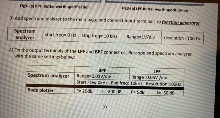
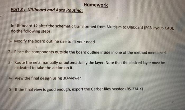
Class work Part1: Frequency response: 1) Use the circuit wizard to design an active Butterworth Band Pass Filter as figure (3-a) in a hierarchical block (BPF1) and Low Pass Filter as figure (3-b) in a hierarchical block (LPF1). Set the input pin to 1, output pin =1 2) On the main page of Multisim project add a function generator and set: Square wave of Vp=5V, frequency to 1 kHz. Then connect the output to the input of the (LPF & BPF). Her Wet Fate Wizard Troel Band The Lowester fande) Pas bando Gandes 10 Pais frequency Stop frequency 2 10 Stop bandan Stop band gain 33 Baa de reg. Low and 2 Hotend pass free High 5.5 Pas banda -1 Stop banda Fierload 50 Restant CAD 1 Topology Die Pau Active Highend stop fred Paw barda- Stop bundan -15 Filter bond: 50 Resistance in: 1 DDB Low and stress and posted 1 High end step free Calculation was y completed Pass frequency Stop frequency Calculation was successfully completed of Type Gutterworth Chebyhev Topology Pasove Active Default setting Baldo venty Close Held Default set Budo ver dose Fig3- (a) BPF Butterworth specification Fig3-(b) LPF Butterworth specification Fig3- (a) BPF Butterworth specification Fig3-(b) LPF Butterworth specification 3) Add spectrum analyzer to the main page and connect input terminals to function generator Spectrum analyzer start freq=0 Hz stop freq= 10 kHz Range=1V/div resolution =100 Hz 4) On the output terminals of the LPF and BPF connect oscilloscope and spectrum analyzer with the same settings below: Spectrum analyzer BPF LPF Range=0.01V/div Range=0.05V /div Start Freq:OkHz, End freq: 10kHz, Resolution:100Hz F= 20dB I= -200 dB F= 5dB I= -50 dB Bode plotter 93 5) Simulate the circuit and watch the result, fill the table below. frequency Input First harmonic (Hz) Function Generator Second harmonic (Hz) First harmonic (Hz) BPF Second harmonic (Hz) First harmonic (Hz) LPF Second harmonic (Hz) amplitude (mv) (mv) (mv) (mv) (mv) (mv) Part 2: Transfer to Ultiboard: 1) Replace the virtual op-amps in the filters by the real op-amp LM324AJ. Note: use the same op-amp IC to replace the four virtual op-amps. 2) Connect #15 Volt to the op-amp LM324AJ. 3) Transfer the circuit to UltiBoard as mentioned. 4) Go back to Multisim and replace the Op-amps in the LPF with different package LM324AD. 5) Do the forward Annotation and Note the changes on the UltiBoard. Homework Part 3: Ultiboard and Auto Routing: In Ultiboard 12 after the schematic transformed from Multisim to Ultiboard (PCB layout-CAD), do the following steps: 1. Modify the board outline size to fit your need. 2- Place the components outside the board outline inside in one of the method mentioned. 3- Route the nets manually or automatically the layer. Note that the desired layer must be activated to take the action on it. 4- View the final design using 3D-viewer. 5. If the final view is good enough, export the Gerber files needed (RS-274-X) Class work Part1: Frequency response: 1) Use the circuit wizard to design an active Butterworth Band Pass Filter as figure (3-a) in a hierarchical block (BPF1) and Low Pass Filter as figure (3-b) in a hierarchical block (LPF1). Set the input pin to 1, output pin =1 2) On the main page of Multisim project add a function generator and set: Square wave of Vp=5V, frequency to 1 kHz. Then connect the output to the input of the (LPF & BPF). Her Wet Fate Wizard Troel Band The Lowester fande) Pas bando Gandes 10 Pais frequency Stop frequency 2 10 Stop bandan Stop band gain 33 Baa de reg. Low and 2 Hotend pass free High 5.5 Pas banda -1 Stop banda Fierload 50 Restant CAD 1 Topology Die Pau Active Highend stop fred Paw barda- Stop bundan -15 Filter bond: 50 Resistance in: 1 DDB Low and stress and posted 1 High end step free Calculation was y completed Pass frequency Stop frequency Calculation was successfully completed of Type Gutterworth Chebyhev Topology Pasove Active Default setting Baldo venty Close Held Default set Budo ver dose Fig3- (a) BPF Butterworth specification Fig3-(b) LPF Butterworth specification Fig3- (a) BPF Butterworth specification Fig3-(b) LPF Butterworth specification 3) Add spectrum analyzer to the main page and connect input terminals to function generator Spectrum analyzer start freq=0 Hz stop freq= 10 kHz Range=1V/div resolution =100 Hz 4) On the output terminals of the LPF and BPF connect oscilloscope and spectrum analyzer with the same settings below: Spectrum analyzer BPF LPF Range=0.01V/div Range=0.05V /div Start Freq:OkHz, End freq: 10kHz, Resolution:100Hz F= 20dB I= -200 dB F= 5dB I= -50 dB Bode plotter 93 5) Simulate the circuit and watch the result, fill the table below. frequency Input First harmonic (Hz) Function Generator Second harmonic (Hz) First harmonic (Hz) BPF Second harmonic (Hz) First harmonic (Hz) LPF Second harmonic (Hz) amplitude (mv) (mv) (mv) (mv) (mv) (mv) Part 2: Transfer to Ultiboard: 1) Replace the virtual op-amps in the filters by the real op-amp LM324AJ. Note: use the same op-amp IC to replace the four virtual op-amps. 2) Connect #15 Volt to the op-amp LM324AJ. 3) Transfer the circuit to UltiBoard as mentioned. 4) Go back to Multisim and replace the Op-amps in the LPF with different package LM324AD. 5) Do the forward Annotation and Note the changes on the UltiBoard. Homework Part 3: Ultiboard and Auto Routing: In Ultiboard 12 after the schematic transformed from Multisim to Ultiboard (PCB layout-CAD), do the following steps: 1. Modify the board outline size to fit your need. 2- Place the components outside the board outline inside in one of the method mentioned. 3- Route the nets manually or automatically the layer. Note that the desired layer must be activated to take the action on it. 4- View the final design using 3D-viewer. 5. If the final view is good enough, export the Gerber files needed (RS-274-X)


