

Question: Consider the ratio control scheme shown in Fig. 15.6. Each flow rate is measured using an orifice plate and a differential pressure (D/P) transmitter. The
dm = dm0 + K1d2
um = um0 + K2u2
Each transmitter output signal has a range of 3€“15 psi. The transmitter spans are denoted by Sd and Su for the disturbance and manipulated flow rates, respectively. Derive an expression for the gain of the ratio station KR in terms of Sd, Su, and the desired ratio Rd.
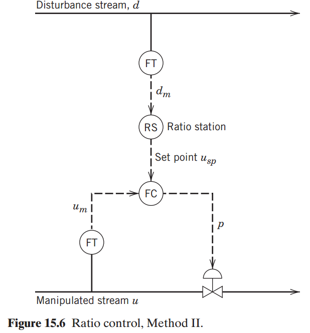
Disturbance stream, d FT dm RS ) Ratio station Set point usp FC I FT Manipulated stream u Figure 15.6 Ratio control, Method II.
Step by Step Solution
3.35 Rating (158 Votes )
There are 3 Steps involved in it
By definition the ratio station sets u m u m0 K R d m d m0 Thu... View full answer

Get step-by-step solutions from verified subject matter experts
Document Format (2 attachments)
1602_606321ef1a045_680403.pdf
180 KBs PDF File
1602_606321ef1a045_680403.docx
120 KBs Word File