

Question: Task 1: Multiple production lines exist in a water bottling factory. The most automated part is the filling line, where plastic bottles are placed on
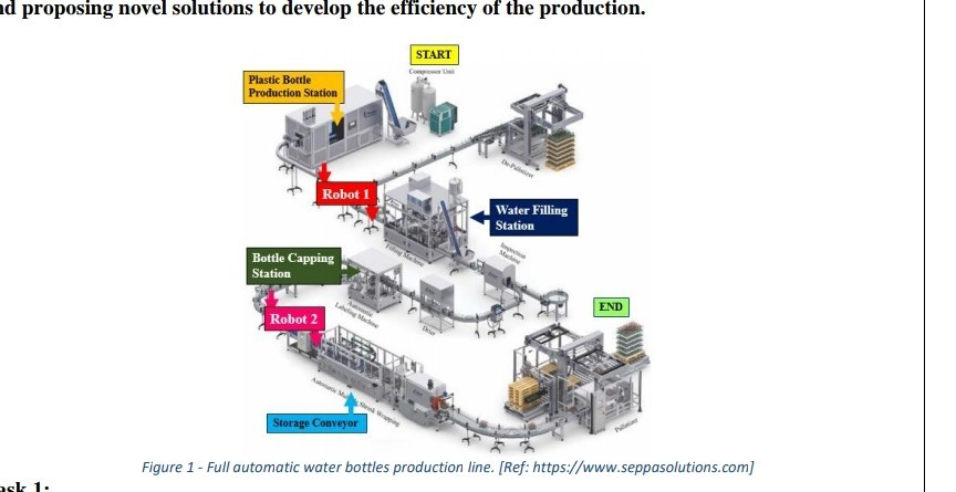
Task 1: Multiple production lines exist in a water bottling factory. The most automated part is the filling line, where plastic bottles are placed on a conveyor belt and driven towards a filling station. The conveyor belt moves at a certain speed that prevents the cylinders from falling due to extreme acceleration or deceleration, and it stops for a while at the filling station, to allow for each bottle to be filled with a predefined amount of water. At the filling station, the conveyor belt stops whenever a bottle is placed accurately below the water nozzle. The time of filling is calculated based on the water flow rate and the volume of the plastic bottle. However, a feedback signal based on the weight of the extinguisher is used to confirm that it is filled with the exact required amount. When the amount of water is satisfactory, the filled bottle leaves the filling station and reaches the capping station, at which the plastic bottle is sealed by pressing a capping piece on top. The capping piece is heated bya steam flow for hygienic reasons and to make the sealing process easier by expanding the cap a little bit. The heat of the steaming chamber is continuously measured, because overheating will melt the plastic cap. The force required to place the cap in its place is provided by a pneumatic jack, which is driven by compressed air. A correct capping process requires the air driving the jack to be fixed at 4 bars. A. Instrumentation systems consist of three main parts, draw a block diagram showing these components. B. The described process has multiple types of sensors including speed, weight, proximity, temperature and pressure sensors. Define each of these sensors by specifying the quantities they measure in this production line. C. Locate the suitable place for each of these sensors on the filling line. D. Describe what problems may arise if each of these instrumentation systems malfunctions or gets omitted from the system. E. You have chosen the following sensing elements to measure the quantities specified in (B): 1. Incremental encoder 2. Load Cell 3. Capacitive proximity switch 4. Thermo-couple. 5. Diaphragm sensor with built-in strain gauges. Clearly explain the principle of operation, use sketches and equations if required. F. In choosing a proper sensor for an application, we refer to its main characteristics including accuracy, resolution, precision, sensitivity and stability. These terms are important for process control engineering, define them in your own words. G. For the examples of sensing elements mentioned in (E), specify a suitable signal processing technique for each device. H. If we are to use the signal in a control system, is it better to send it as 4-20 mA current signal or 0-5 Vvoltage signal? Explain why.
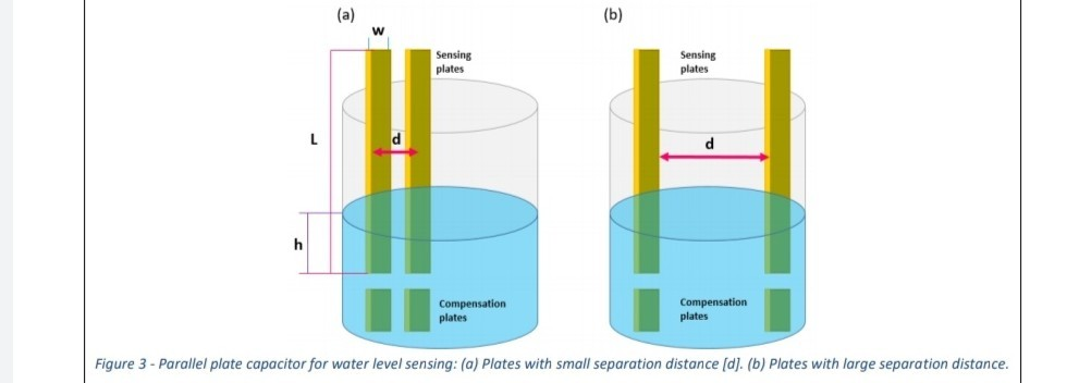
B. A parallel plate capacitive element that can be installed inside the water tank. The height of the water will change the permittivity between the plates. By measuring the total capacitance, between the plates, it is possible to know the water level. i. Explain how a parallel plate capacitor can be used as a sensing element in general. What are the parameters that can be changed in a parallel plate capacitor to use it for sensing? ii. In order to measure the output capacitance practically, would you apply a DC or AC voltage? iii. In the water level case, what is the variable parameter in the parallel plate capacitor? iv. Why do we need a compensation parallel plate capacitor, as shown in Fig. 3? v. Deduce an expression for the equivalent capacitance if measured between the two parallel plates. Hint: are they parallel or series? Label the height of the plates as L [constant] and the height of water as h [variable]. vi. You had an argument with one of the engineers, on wither to install the parallel plates on the inner sides of the tank [Fig. 3(b) large separation], or have them placed in the middle of tank with a tiny separation between them [Fig3(a)]. You thought that sensitivity of measurement is the best way to examine this argument. Assume that the tank is full, so the permittivity is constant along the plates. Write down an expression for the sensitivity of the sensor in terms of the separation distance? vii. Use a software tool such as Excel or Matlab to draw the Sensitivity versus the separation distance of the plates. Comment on the results, which configuration is better for operation, the small or large separation distance?
Task 3: You have received two load cells as samples to be used for the water level measurement. You were asked to examine the accuracy of the two sensors:
i. You tested the two products by measuring a standard calibration weight of 20 kg. The two instruments gave the following readings after repeating the measurement few times. Which one is more suitable for your production line? Hint: use a software to draw the data-points and visualize the distribution.
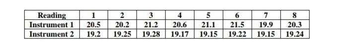
ii. Calibration has been done to the two instruments such that the average value of the instrument reading now corresponds to the true value of the calibration sample. Which instrument is more accurate after the calibration? Which one is more precise? Which one would you use? iii. You have noticed that one of the sensors is produced few years ago. To ensure it is still working will, you compared your test results with the manufacturers datasheet, to have an idea of the stability of the instrument. Assuming the calibration weights are identical, comment on the stability of the instrument? How does this affect accuracy? What has changed with time in terms of the instrument behaviour? Hint: use a software to draw the data at the time of production and the new testing data, model those using simple equations and comment on the differences
.

Task 1: You have been assigned the task of designing and developing the temperature control system within the Martian homes. The dome has a single door which is commonly used few tens of times a day for Martian settlers to practice, explore the surrounding area and perform research tasks. Throughout the process of door opening, many vital variables are changed such as the chamber pressure, oxygen levels and for your main concern the temperature. Also, the material of this Martian home is heat isolating, but as there is no perfect heat-isolating material, continuous heat flow occurs to and from the chamber to the surroundings. A. Control systems in general can handle three main tasks, what are they? B. What happens if we do not control the temperature within the chambers? For example, if we set the temperature for 25 degrees C when we build this Martian home, then leave the temperature un-controlled? C. Control systems can be categorized into open-loop and closed-loop systems, define each of these categories and sketch the generic block diagram for each case defining the information paths and the signals in each case? D. Would you recommend using an open or closed loop system to monitor the temperature within the Martian home, explain your answer? E. The average surface temperature on Mars is -63 C, so temperature control is used to drive a heating element, or a heater, inside the Martian home. After choosing to wither this system is open or closed loop, and based on your choice of a sensor if required, draw a block diagram of the control system. Define the information paths, process controller and the signals on the block diagram. F. In order to choose the correct process controller and determine its specifications, as a designer you are required to evaluate the acceptable dead time and lag that is allowed in your process, considering the system capacitance. For example, if the temperature drops suddenly and your system takes too long to return the temperature to its set value, the astronauts will probably die freezing! What is meant by dead time, process lag, control lag and Capacitance? G. Now you have enough background to move to the actual design of the process controller. The researchers in your department had different views on either using a discrete-state controller or an analogue controller. For the analogue controller, a proportional and integral mode controller was suggested. i. Explain with your own words the advantages of using an analogue controller over a discrete-state controller. Draw rough sketches showing the relation between the set- value and the measured value for each case. ii. Assume that you are using a PI controller and the system is stable at 25 C, before an astronaut comes from the outside decreasing the home temperature to 15 C. Plot a rough sketch of the temperature response showing the P response alone, and another one showing the PI response when the system corrects the temperature back to the set value.
H. What is the main problem expected upon using a PI controller? Suggest an improvement on the process controller used in order to optimize the design of the control system? What is the effect of your new design on the performance? Explain using your own words and sketches.
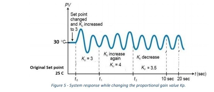
Task 2: A prototype of the Martian home was built for testing with your temperature control system using an analogue PI temperature controller. In order to test the system stability under temperature disturbances, you were asked to tune the PI controller. A. Why do we need to tune the PI controller? Why is it necessary? B. Name two system tuning techniques and briefly describe the tuning process in each case, using your own words. C. You decided to use a method based on the closed-loop critical cycle criteria. You have tuned the proportional gain factor until you observed the following response curve. Find the suitable tuned values of gain factors for your PI operation, refer to the suitable tables.
D. Using the gain values obtained in (C), comment on the control system efficiency if operated in a P mode and PI mode, by calculating the controller output signal corresponding to a linear error signal starting at time zero with a slope of 2%/s. Calculate the output signal after zero and 2 seconds from the beginning of the error as an example. What is the difference between using a P and a PI mode in terms of the controller output signal? Which mode is more efficient in correcting the output value to match the set value? Can you suggest any other modifications to further improve the effectiveness of your system? Show by providing calculations.
E. Is it effective to control the temperature within a Martian home using a closed-loop system of a single temperature sensor, a heater and an analogue controller? If you do not think so, how would you propose enhancing the efficiency of this system? Suggest some modifications on the control system, or even on the Martian home design to support your point of view.
ad proposing novel solutions to develop the efficiency of the production. START Plastic Bottle Production Station Robot 1 Water Filling Station Bottle Capping Station END Robot 2 Storage Conveyor Figure 1 - Full automatic water bottles production line. [Ref: https://www.seppasolutions.com] ask 1 (a) (b) w Sensing plates Sensing plates L d d h Compensation plates Compensation plates Figure 3 - Parallel plate capacitor for water level sensing: (a) Plates with small separation distance (d). (b) Plates with large separation distance. Reading Instrument 1 Instrument 2 1 20.5 19.2 2 20.2 19.25 3 21.2 19.28 4 20.6 19.17 5 21.1 19.15 6 21.5 19.22 7 19.9 19.15 8 20.3 19.24 Reading Instrument 1 Instrument 2 1 20.5 19.2 2 20.2 19.25 3 21.2 19.28 4 20.6 19.17 5 21.1 19.15 6 21.5 19.22 7 19.9 19.15 8 20.3 19.24 PV Set point changed and increased to 3 30 C mm K increase K = 3 again K decrease Original Set point K = 4 K = 3.5 25 C (sec) to ta 10 sec 20 sec Figure 5 - System response while changing the proportional gain value Kp. ad proposing novel solutions to develop the efficiency of the production. START Plastic Bottle Production Station Robot 1 Water Filling Station Bottle Capping Station END Robot 2 Storage Conveyor Figure 1 - Full automatic water bottles production line. [Ref: https://www.seppasolutions.com] ask 1 (a) (b) w Sensing plates Sensing plates L d d h Compensation plates Compensation plates Figure 3 - Parallel plate capacitor for water level sensing: (a) Plates with small separation distance (d). (b) Plates with large separation distance. Reading Instrument 1 Instrument 2 1 20.5 19.2 2 20.2 19.25 3 21.2 19.28 4 20.6 19.17 5 21.1 19.15 6 21.5 19.22 7 19.9 19.15 8 20.3 19.24 Reading Instrument 1 Instrument 2 1 20.5 19.2 2 20.2 19.25 3 21.2 19.28 4 20.6 19.17 5 21.1 19.15 6 21.5 19.22 7 19.9 19.15 8 20.3 19.24 PV Set point changed and increased to 3 30 C mm K increase K = 3 again K decrease Original Set point K = 4 K = 3.5 25 C (sec) to ta 10 sec 20 sec Figure 5 - System response while changing the proportional gain value Kp
Step by Step Solution
There are 3 Steps involved in it

Get step-by-step solutions from verified subject matter experts