A USB (universal serial bus) connector can power its devices at 5 volts and 1 amp. In a certain portable product, it is desired to
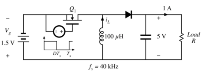
A USB (universal serial bus) connector can power its devices at 5 volts and 1 amp. In a certain portable product, it is desired to provide this power from a 1.5 V battery. It is decided to employ a buck-boost converter to increase the 1.5 V battery voltage to the required 5 V. The power converter schematic is illustrated below.

A suitable transistor is found having an on-resistance of Ron = 8 milliohms, and a Schottky diode is found that has a forward voltage drop of Vd = 0.4 V. The on-resistance of the Schottky diode may be ignored.
For this problem, you must employ the methods discussed in the Chapter 3 lectures, to analyze this converter and find analytical expressions for the output voltage, inductor current, etc., as well as to derive an equivalent circuit that can be solved for the converter efficiency. You are asked to enter expressions for intermediate steps in your analysis; these expressions must be entered as computer-readable equations using the exact variable names as defined below:
Input voltage Vg Output voltage V Duty cycle D Load resistance R Inductor current IL MOSFET on-resistance Ron Diode forward voltage drop Vd Inductor winding resistance RL
If necessary, manipulate your model into the form shown below. The quantity IL is the dc component of the inductor current.

you are asked to enter mathematical expressions for the elements in this model. The effective turns ratios are functions of only the duty cycle D. while the effective loss elements Re and ye are functions of the duty cycle D and the loss elements, but no other Quantities.
Derive an expression for the conversion ratio V/Vg. Express your result in terms of Vg, D, RL, Ron, Vd, and R, and enter the result below.
Derive an expression for the converter efficiency. Express your result in terms of Vg. D, RL, Ron, Vd, and R, and enter the result below.
It is desired that the converter efficiency be at least 85% under nominal conditions, i.e., when the input voltage is 1.5 V and the output is 5 Vat 1 A. How large (in ohms) can the inductor resistance be? Again, enter this and other numerical values with an accuracy of at least plus or minus 0.1%.
1.5 V 21 DT, T, ele L 100 H f = 40 kHz = 1 A SV Load R Vg 1:ml iepe ege Re IL +1 Ve 1:m2 ope lege + V I 3R
Step by Step Solution
3.37 Rating (163 Votes )
There are 3 Steps involved in it
Step: 1
On state resistance of switch Ron 8 m Diode voltage vd 04 V On state when switch is closed Vg 8 ...
See step-by-step solutions with expert insights and AI powered tools for academic success
Step: 2

Step: 3

Document Format ( 2 attachments)
6092769673a4e_21188.pdf
180 KBs PDF File
6092769673a4e_21188.docx
120 KBs Word File
Ace Your Homework with AI
Get the answers you need in no time with our AI-driven, step-by-step assistance
Get Started


