Question
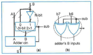
Create a structural HDL description of the 4-bit adder/subtractor circuit in Figure 4.54(b). Be sure to first create a behavioral HDL description of each component
Create a structural HDL description of the 4-bit adder/subtractor circuit in Figure 4.54(b). Be sure to first create a behavioral HDL description of each component used in your structural HDL design. Figure 4.54 Two's complement adder/subtractor using a mux, (b) alternative circuit for Busing XOR gates. 
0 1 N-bit 2x1 B A Adder cin s B N-bit -sub b7 b6 adder's B inputs (b) sub
Step by Step Solution
3.41 Rating (157 Votes )
There are 3 Steps involved in it
Step: 1
VHDL program The behavioral program for the XOR ...
Get Instant Access to Expert-Tailored Solutions
See step-by-step solutions with expert insights and AI powered tools for academic success
Step: 2

Step: 3

Ace Your Homework with AI
Get the answers you need in no time with our AI-driven, step-by-step assistance
Get StartedRecommended Textbook for
A Pathway To Introductory Statistics
Authors: Jay Lehmann
1st Edition
0134107179, 978-0134107172
Students also viewed these Programming questions
Question
Answered: 1 week ago
Question
Answered: 1 week ago
Question
Answered: 1 week ago
Question
Answered: 1 week ago
Question
Answered: 1 week ago
Question
Answered: 1 week ago
Question
Answered: 1 week ago
Question
Answered: 1 week ago
Question
Answered: 1 week ago
Question
Answered: 1 week ago
Question
Answered: 1 week ago
Question
Answered: 1 week ago
Question
Answered: 1 week ago
Question
Answered: 1 week ago
Question
Answered: 1 week ago
Question
Answered: 1 week ago
Question
Answered: 1 week ago
Question
Answered: 1 week ago
Question
Answered: 1 week ago
Question
Answered: 1 week ago
Question
Answered: 1 week ago
View Answer in SolutionInn App


