Answered step by step
Verified Expert Solution
Question
1 Approved Answer
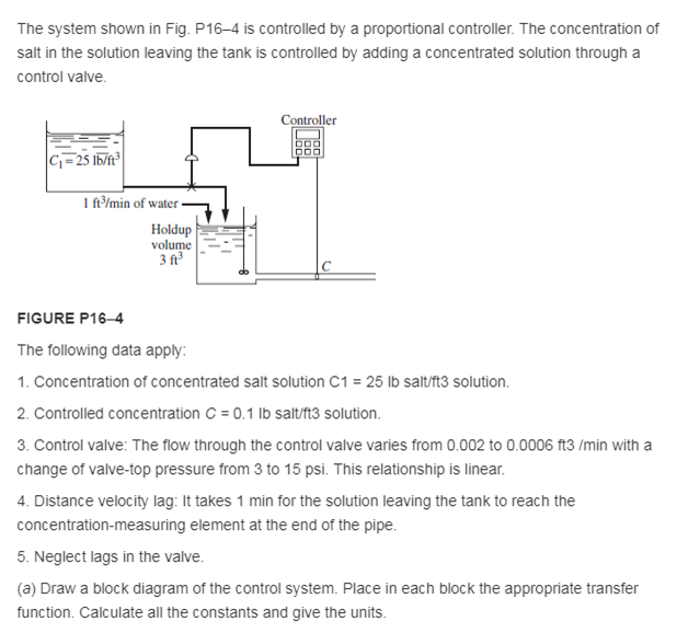
The system shown in Fig. P16-4 is controlled by a proportional controller. The concentration of salt in the solution leaving the tank is controlled


The system shown in Fig. P16-4 is controlled by a proportional controller. The concentration of salt in the solution leaving the tank is controlled by adding a concentrated solution through a control valve. C=25 lb/ft 1 ft/min of water Holdup volume 3 ft Controller FIGURE P16-4 The following data apply: 1. Concentration of concentrated salt solution C1 = 25 lb salt/ft3 solution. 2. Controlled concentration C = 0.1 lb salt/ft3 solution. 3. Control valve: The flow through the control valve varies from 0.002 to 0.0006 ft3/min with a change of valve-top pressure from 3 to 15 psi. This relationship is linear. 4. Distance velocity lag: It takes 1 min for the solution leaving the tank to reach the concentration-measuring element at the end of the pipe. 5. Neglect lags in the valve. (a) Draw a block diagram of the control system. Place in each block the appropriate transfer function. Calculate all the constants and give the units. (b) Using a frequency-response diagram and the Ziegler-Nichols rules, determine the settings of the controller. (c). Using the controller settings of part (b), calculate the offset when the set point is changed by 0.02 unit of concentration.
Step by Step Solution
★★★★★
3.57 Rating (164 Votes )
There are 3 Steps involved in it
Step: 1

Get Instant Access to Expert-Tailored Solutions
See step-by-step solutions with expert insights and AI powered tools for academic success
Step: 2

Step: 3

Ace Your Homework with AI
Get the answers you need in no time with our AI-driven, step-by-step assistance
Get Started


