Answered step by step
Verified Expert Solution
Question
1 Approved Answer
1. [20%] The inductive time constant. In is given by: L IRL: E- ['11] Measurements are made using the circuit shown in Figure 1. By
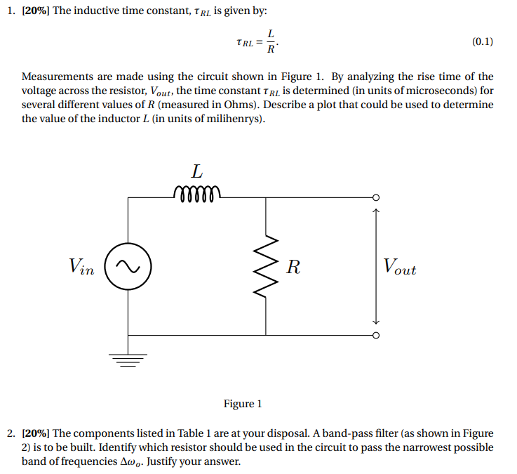
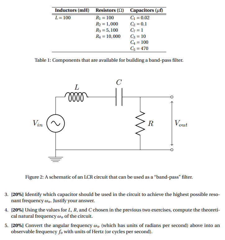
1. [20%] The inductive time constant. In is given by: L IRL: E- ['11] Measurements are made using the circuit shown in Figure 1. By analyzing the rise time of the voltage across the resistor. limb the time constant rim is determined {in units of microseconds} for several different values of R [measured in Ohms]. Describe a plot that could be used to determine the value of the inductor L {in units of milihenrys]. Figurel 2. [20%] The components listed in Table 1 are at your disposal. A band-pass lter [as shown in Figure 2} is to be but. Identifyr which resistor should be used in the circuit to pass the narrowest possible band of frequencies drug. Justify your answer. Inductors (mi) Resistors (() Capacitors (uf) L = 100 R1 = 100 C1 = 0.02 R2 = 1,000 C2 = 0.1 R3 = 5, 100 C7 = 1 R4 = 10,000 C3 = 10 C4 = 100 C5 = 470 Table 1: Components that are available for building a band-pass filter. C L 6000 Vin N R. Vout Figure 2: A schematic of an LCR circuit that can be used as a "band-pass" filter. 3. [20%] Identify which capacitor should be used in the circuit to achieve the highest possible reso- nant frequency wo. Justify your answer. 4. [20%] Using the values for L, R, and C chosen in the previous two exercises, compute the theoreti- cal natural frequency wo of the circuit. 5. [20%] Convert the angular frequency wo (which has units of radians per second) above into an observable frequency fo with units of Hertz (or cycles per second)
Step by Step Solution
There are 3 Steps involved in it
Step: 1
Get Instant Access to Expert-Tailored Solutions
See step-by-step solutions with expert insights and AI powered tools for academic success
Step: 2
Step: 3
Ace Your Homework with AI
Get the answers you need in no time with our AI-driven, step-by-step assistance
Get Started