1. A sequential circuit has two inputs (A 1 and A 0 ) and one output (B). The output B = 1 every time the
- 1. A sequential circuit has two inputs (A1 and A0) and one output (B). The output B = 1 every time the input pattern “312” (11/01/10) is observed. Otherwise B is 0.
- a) Assuming the circuit is implemented as a Moore machine, draw the corresponding state diagram.
b) Obtain the state diagram (Use binary encoding to represent states).
c) Derive flip-flop and output equations. Use D flip-flops. Do not draw the circuit.
2.A sequential circuit has two inputs (A1 and A0) and one output (B). The output B = 1 every time the input pattern “312” (11/01/10) is observed. Otherwise B is 0. This is the same circuit as in the previous question. Now draw the state diagram using Mealy machine approach.
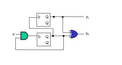
- 3. Consider the following sequential circuit and the timing values, tP,FF = tP,XOR = 200.0 ps, tP,AND = ts = 100.0 ps, and th = 150.0 ps.

a. Find the maximum clock frequency that can be applied to the circuit.
b. Is hold time violated in the circuit? Why or why not? Express the hold time violation condition.
- 4. F(x, y, z, t) = P (0, 1, 4, 6, 8, 9, 10, 12, 14, 15)
- a. Implement the circuit using a decoder and an or gate.
b. Implement the circuit using the smallest multiplexer. (Do not use any other logical element)
X D Q D Q Y Yo
Step by Step Solution
3.61 Rating (176 Votes )
There are 3 Steps involved in it
Step: 1
The detailed answer for the above question is provided below 1a The state diagram for a Moore machine with two inputs A1 and A0 and one output B can b...
See step-by-step solutions with expert insights and AI powered tools for academic success
Step: 2

Step: 3

Ace Your Homework with AI
Get the answers you need in no time with our AI-driven, step-by-step assistance
Get Started


