Answered step by step
Verified Expert Solution
Question
1 Approved Answer
1) A static seismic analysis using Q = 2 and c = 0.36 tells us that the basal shear of the floor plan of


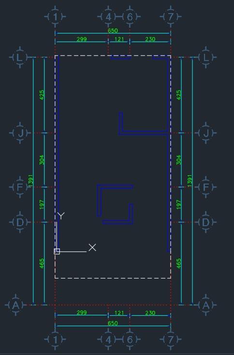
1) A static seismic analysis using Q = 2 and c = 0.36 tells us that the basal shear of the floor plan of the Task6_Mamposteria_2023.dwg file is 14ton. You must obtain the total shear of all walls in the X-X direction of the plan and design them by shear of the floor plan and design them for shear including torsional shear (you are not allowed to use the simplified NTCS or NTCM methods are not allowed to be used). Valid assumptions: You can consider only the accidental eccentricity due to an offset. of the center of mass 5% towards the top of the floor and the shear caused by the shear caused by the earthquake acting only in the X-X direction. X-X DIRECTION ONLY. In other words, you can ignore the requirement to apply 30% of the shear in the transverse direction. of the shear in the transverse (Y-Y) direction. The masonry is of brick slab bonded with type Il mortar, so the compressive strength of the masonry is 10kg/cm2. In addition, the shear strength is equal to 3kg/cm2. In estimating the stiffness of the walls consider the flexural and shear contribution corresponding to E = 9,000kg/cm2, G = 3,600kg/cm2, B=0, x= 1.2. The axial load of all walls is 2,000kg/m. The height of the walls is equal to 2.7m and their width is 14cm. The white projection indicated is the slab limit. In case any wall does not have sufficient shear capacity you should place horizontal reinforcement with rods. Results to report: Center of masses, the center of stiffness of the floor, the static eccentricity, and the total eccentricity (including accidental). In addition, you must submit a table indicating for each wall (using the numbering indicated on the floor plan): 1. direct shear 2. Torsional shear 3. Total shear 4. Resistant shear of masonry 5. Resistant shear including rebar reinforcement (if necessary). IFT OF D 1391 425 304 197 $9+ 1) 417 299 X 299 4416) 650 167 650 T 44H6T TT 230 230 477 425 304 261 465 477 1391 KFY AH
Step by Step Solution
There are 3 Steps involved in it
Step: 1
A qualified structural engineer would consider several key parameters in the analysis of a structural system especially in the context of seismic design Some of the key parameters include 1 Seismic De...
Get Instant Access to Expert-Tailored Solutions
See step-by-step solutions with expert insights and AI powered tools for academic success
Step: 2

Step: 3

Ace Your Homework with AI
Get the answers you need in no time with our AI-driven, step-by-step assistance
Get Started


