Answered step by step
Verified Expert Solution
Question
1 Approved Answer
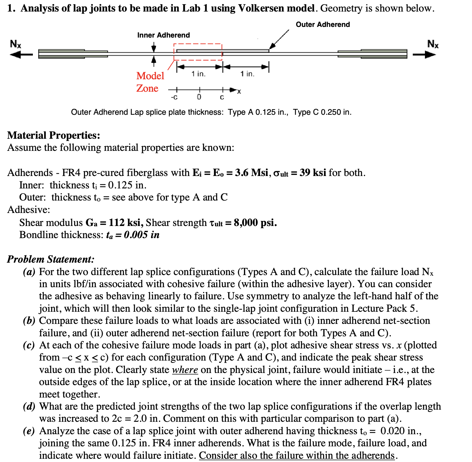
1. Analysis of lap joints to be made in Lab 1 using Volkersen model. Geometry is shown below. Outer Adherend Nx Inner Adherend Model

1. Analysis of lap joints to be made in Lab 1 using Volkersen model. Geometry is shown below. Outer Adherend Nx Inner Adherend Model Zone + -C 1 in. + 0 C 1 in. Outer Adherend Lap splice plate thickness: Type A 0.125 in., Type C 0.250 in. Material Properties: Assume the following material properties are known: Adherends - FR4 pre-cured fiberglass with E; = Eo = 3.6 Msi, Tult = 39 ksi for both. Inner: thickness t; = 0.125 in. Outer: thickness to: = see above for type A and C Adhesive: Shear modulus Ga = 112 ksi, Shear strength Tult = 8,000 psi. Bondline thickness: ta = 0.005 in Nx Problem Statement: (a) For the two different lap splice configurations (Types A and C), calculate the failure load Nx in units lbf/in associated with cohesive failure (within the adhesive layer). You can consider the adhesive as behaving linearly to failure. Use symmetry to analyze the left-hand half of the joint, which will then look similar to the single-lap joint configuration in Lecture Pack 5. (b) Compare these failure loads to what loads are associated with (i) inner adherend net-section failure, and (ii) outer adherend net-section failure (report for both Types A and C). (c) At each of the cohesive failure mode loads in part (a), plot adhesive shear stress vs. x (plotted from -c x c) for each configuration (Type A and C), and indicate the peak shear stress value on the plot. Clearly state where on the physical joint, failure would initiate - i.e., at the outside edges of the lap splice, or at the inside location where the inner adherend FR4 plates meet together. (d) What are the predicted joint strengths of the two lap splice configurations if the overlap length was increased to 2c = 2.0 in. Comment on this with particular comparison to part (a). (e) Analyze the case of a lap splice joint with outer adherend having thickness to= 0.020 in., joining the same 0.125 in. FR4 inner adherends. What is the failure mode, failure load, and indicate where would failure initiate. Consider also the failure within the adherends.
Step by Step Solution
★★★★★
3.53 Rating (150 Votes )
There are 3 Steps involved in it
Step: 1
To solve this problem well use the Volkersen model for lap joints Here are the steps to address each ...
Get Instant Access to Expert-Tailored Solutions
See step-by-step solutions with expert insights and AI powered tools for academic success
Step: 2

Step: 3

Ace Your Homework with AI
Get the answers you need in no time with our AI-driven, step-by-step assistance
Get Started


