Answered step by step
Verified Expert Solution
Question
1 Approved Answer
1. Assuming that inside the control unit there are internal signals denoting which instruction has just been decoded, for example: r_type_dec is high when the
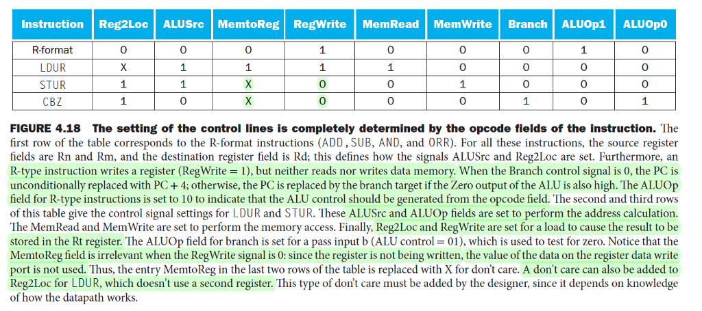
1. Assuming that inside the control unit there are internal signals denoting which instruction has just been decoded, for example: r_type_dec is high when the instruction is R_type, similarly there is ldur_dec, stur_dec, b_dec and cbz_dec. Now consider the signal ALUSrc, it can be derived as (ldur_dec + stur_dec) from Figure 4.18 (these are the entries with logic 1 rows). Similarly, ALUOp1 can be derived as (r_type_dec).
(a)Derive the logic expressions for all the signals in the table.
(b)Why do a couple of columns have xs?
Instruction Reg2Loc ALUSrc MemtoReg RegWrite MemRead MemWrite Branch ALUOp1 ALUOpO R-format LDUR STUR CBZ 0 0 0 0 0 0 0 0 1 0 0 0 0 1 0 FIGURE 4.18 The setting of the control lines is completely determined by the opcode fields of the instruction. The first row of the table corresponds to the R-format instructions (ADD, SUB, AND, and ORR). For all these instructions, the source register fields are Rn and Rm, and the destination register field is Rd; this defines how the signals ALUSrc and Reg2Loc are set. Furthermore, an R-type instruction writes a register (RegWrite 1), but neither reads nor writes data memory. When the Branch control signal is 0, the PC is unconditionally replaced with PC+4; otherwise, the PC is replaced by the branch target if the Zero output of the ALU is also high. The ALUO]p field for R-type instructions is set to 10 to indicate that the ALU control should be generated from the opcode field. The second and third rows of this table give the control signal settings for LDUR and STUR. These ALUSrc and ALUOp fields are set to perform the address calculation The MemRead and MemWrite are set to perform the memory access. Finally, Reg2Loc and RegWrite are set for a load to cause the result to be stored in the Rt register. The ALUOp field for branch is set for a pass input b (ALU control-01), which is used to test for zero. Notice that the MemtoReg field is irrelevant when the RegWrite signal is 0: since the register is not being written, the value of the data on the register data write port is not used. Thus, the entry MemtoReg in the last two rows of the table is replaced with X for don't care. A don't care can also be added to Reg2Loc for LDUR, which doesn't use a second register. This type of don't care must be added by the designer, since it depends on knowledge of how the datapath works
Step by Step Solution
There are 3 Steps involved in it
Step: 1

Get Instant Access to Expert-Tailored Solutions
See step-by-step solutions with expert insights and AI powered tools for academic success
Step: 2

Step: 3

Ace Your Homework with AI
Get the answers you need in no time with our AI-driven, step-by-step assistance
Get Started


