Answered step by step
Verified Expert Solution
Question
1 Approved Answer
1. Build the circuit in figure 9, preform a transient analysis simulation 2. Set up the sinusoidal voltage source such that the phase difference
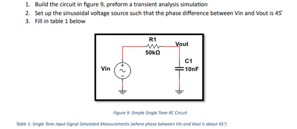
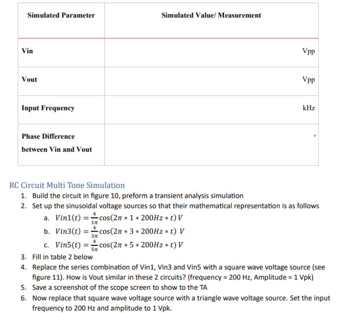
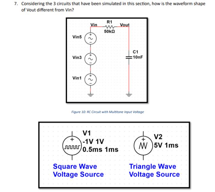
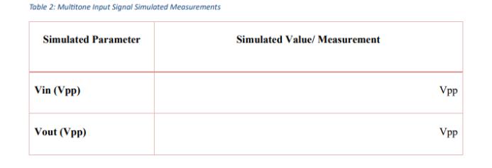
1. Build the circuit in figure 9, preform a transient analysis simulation 2. Set up the sinusoidal voltage source such that the phase difference between Vin and Vout is 45 3. Fill in table 1 below Vin R1 www Vout 50 C1 10nF Figure 9: Simple Single Tone RC Circuit Table 1: Single Tone Input Signal Simulated Measurements (where phase between Vin and Vout is about 45) Simulated Parameter Simulated Value/ Measurement Vin Vout Input Frequency Phase Difference between Vin and Vout Vpp Vpp kHz 0 RC Circuit Multi Tone Simulation 1. Build the circuit in figure 10, preform a transient analysis simulation 2. Set up the sinusoidal voltage sources so that their mathematical representation is as follows a. Vin1(t) = cos(2 * 1 * 200Hz *t) V 177 b. Vin3(t) cos(2 *3* 200Hz t) V c. Vin5(t) =cos(2 * 5 * 200Hz t) V 3. Fill in table 2 below St 4. Replace the series combination of Vin1, Vin3 and Vin5 with a square wave voltage source (see figure 11). How is Vout similar in these 2 circuits? (frequency = 200 Hz, Amplitude = 1 Vpk) 5. Save a screenshot of the scope screen to show to the TA 6. Now replace that square wave voltage source with a triangle wave voltage source. Set the input frequency to 200 Hz and amplitude to 1 Vpk. 7. Considering the 3 circuits that have been simulated in this section, how is the waveform shape of Vout different from Vin? Vin5 Vin3 Vin1 R1 Vin Vout w 50kQ 2. 2 C1 10nF Figure 10: RC Circuit with Multitone Input Voltage + V1 -1V 1V 0.5ms 1ms V2 M 5V 1ms Square Wave Voltage Source Triangle Wave Voltage Source Table 2: Multitone Input Signal Simulated Measurements Simulated Parameter Vin (Vpp) Vout (Vpp) Simulated Value/ Measurement Vpp Vpp
Step by Step Solution
There are 3 Steps involved in it
Step: 1

Get Instant Access to Expert-Tailored Solutions
See step-by-step solutions with expert insights and AI powered tools for academic success
Step: 2

Step: 3

Ace Your Homework with AI
Get the answers you need in no time with our AI-driven, step-by-step assistance
Get Started


