

Answered step by step
Verified Expert Solution
Question
1 Approved Answer
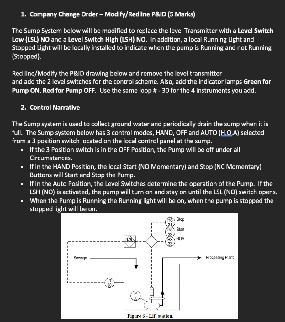
1. Company Change Order - Modify/Redline P&ID (5 Marks) The Sump System below will be modified to replace the level Transmitter with a Level Switch
Step by Step Solution
There are 3 Steps involved in it
Step: 1

Get Instant Access to Expert-Tailored Solutions
See step-by-step solutions with expert insights and AI powered tools for academic success
Step: 2

Step: 3
Ace Your Homework with AI
Get the answers you need in no time with our AI-driven, step-by-step assistance
Get Started
Marketing Database Analytics
Authors: Andrew D. Banasiewicz
1st Edition
0415657881, 978-0415657884