Answered step by step
Verified Expert Solution
Question
1 Approved Answer
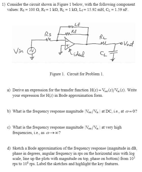
1) Consider the circuit shown in Figure 1 below, with the following component values: Rs = 100 Q, R;= 1 kQ, R = 1


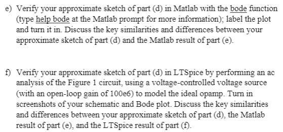
1) Consider the circuit shown in Figure 1 below, with the following component values: Rs = 100 Q, R;= 1 kQ, R = 1 kQ, L;= 15.92 mH, C = 1.59 nF. Vin Rs Rideal RL ML Io vout I CL Figure 1. Circuit for Problem 1. a) Derive an expression for the transfer function H(s) = Vour (S)/V (S). Write your expression for H(s) in Bode approximation form. b) What is the frequency response magnitude Vor/Vin at DC, i.e., at e) Verify your approximate sketch of part (d) in Matlab with the bode function (type help bode at the Matlab prompt for more information); label the plot and turn it in. Discuss the key similarities and differences between your approximate sketch of part (d) and the Matlab result of part (e). f) Verify your approximate sketch of part (d) in LTSpice by performing an ac analysis of the Figure 1 circuit, using a voltage-controlled voltage source (with an open-loop gain of 100e6) to model the ideal opamp. Turn in screenshots of your schematic and Bode plot. Discuss the key similarities and differences between your approximate sketch of part (d), the Matlab result of part (e), and the LTSpice result of part (f).
Step by Step Solution
There are 3 Steps involved in it
Step: 1

Get Instant Access to Expert-Tailored Solutions
See step-by-step solutions with expert insights and AI powered tools for academic success
Step: 2

Step: 3

Ace Your Homework with AI
Get the answers you need in no time with our AI-driven, step-by-step assistance
Get Started


