Question
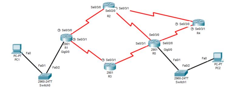
1) Design the following topology in packet tracer and perform the following tasks. Provide screenshot of the topology from cisco packet tracer. a) Configure all
1) Design the following topology in packet tracer and perform the following tasks. Provide screenshot of the topology from cisco packet tracer.

a) Configure all interfaces by sub netting the given network address 192.168.20.0. Provide screenshots of the interface configuration from all the devices.
b) Configure RIPv2 in R1, R3 and R5. Provide screenshots from the CLI of R1, R3 and R5.
c) Verify if all interfaces can communicate each other. Justify your answer. Provide screenshot of the verification result and your answer.
d) Verify if PC1 can communicate with PC2. Trace the route from PC1 to PC2 with proper explanation. Provide screenshot of the verification result and your answer.
PC-PT PC1 Fa0 Fa0/1 2960-24TT Switch0 S60/3/0 Fa0/2 2901 R1 Gig0/0 Se0/3/1 Se0/3/0 Se0/2/0 R2 Se0/3/1 2901 R3 Se0/3/1 Se0/3/1 Se0/3/0 Se0/2/0 2901 Gigo/0 R5 Se0/3/0 Fa0/1 Fa0/2 2960-24TT Switch1 Se0/3/1 R4 Fa0 PC-PT PC2
Step by Step Solution
There are 3 Steps involved in it
Step: 1
Subnet name Needed size Allocated size Address mask Dec Mask Assignable Range Broadcast VLAN PC1Server A 10 14 1921681016 28 255255255240 1921681017 1921681030 1921681031 VLAN PC2ServerB 10 14 1921681...
Get Instant Access to Expert-Tailored Solutions
See step-by-step solutions with expert insights and AI powered tools for academic success
Step: 2

Step: 3

Ace Your Homework with AI
Get the answers you need in no time with our AI-driven, step-by-step assistance
Get Started


