Answered step by step
Verified Expert Solution
Link Copied!

Question

1 Approved Answer

1. Draw the logic diagram of the digit circuit specified by the following Verilog description: module Circuit A (A, B, C, D, F); input A,
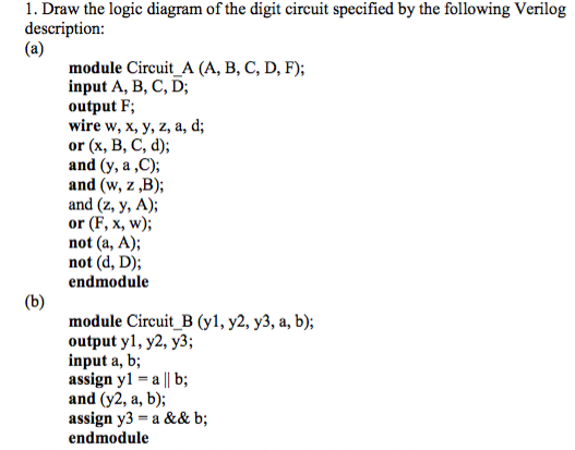
image text in transcribed

1. Draw the logic diagram of the digit circuit specified by the following Verilog description: module Circuit A (A, B, C, D, F); input A, B, C, D; output F; wire w, x, y, z, a, d; or (x, B, C, d); and (y, a,C); and (w, z,B); and (z, y, A); or (F, x, w); not (a, A); not (d, D); endmodule module Circuit B (y1, y2, y3, a, b); output y1, y2, y3; input a, b; assign yl-al| b; and (y2, a, b); assign y3-a && b; endmodule

Step by Step Solution

There are 3 Steps involved in it

Step: 1

blur-text-image

Get Instant Access to Expert-Tailored Solutions

See step-by-step solutions with expert insights and AI powered tools for academic success

Step: 2

blur-text-image

Step: 3

blur-text-image

Ace Your Homework with AI

Get the answers you need in no time with our AI-driven, step-by-step assistance

Get Started

Recommended Textbook for

Practical Database Programming With Visual Basic.NET

Authors: Ying Bai

1st Edition

0521712351, 978-0521712354

More Books

Students also viewed these Databases questions

Question

=+2 Why did OBI create Centers of Excellence?

Answered: 1 week ago