Question
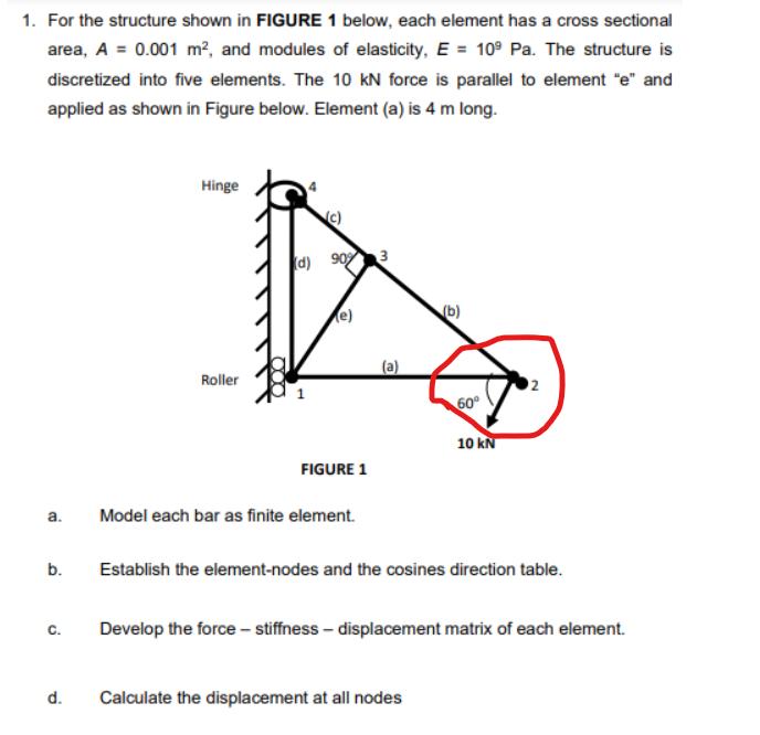
1. For the structure shown in FIGURE 1 below, each element has a cross sectional area, A = 0.001 m, and modules of elasticity,


1. For the structure shown in FIGURE 1 below, each element has a cross sectional area, A = 0.001 m, and modules of elasticity, E = 109 Pa. The structure is discretized into five elements. The 10 kN force is parallel to element "e" and applied as shown in Figure below. Element (a) is 4 m long. a. b. C. d. Hinge Roller 000 (d) 90% 3 (e) FIGURE 1 Model each bar as finite element. (b) 60 Calculate the displacement at all nodes 10 kN Establish the element-nodes and the cosines direction table. Develop the force - stiffness-displacement matrix of each element. N098 Nooos== www xsy They
Step by Step Solution
3.45 Rating (168 Votes )
There are 3 Steps involved in it
Step: 1
Answer The solution is provided in the images be...
Get Instant Access to Expert-Tailored Solutions
See step-by-step solutions with expert insights and AI powered tools for academic success
Step: 2

Step: 3

Ace Your Homework with AI
Get the answers you need in no time with our AI-driven, step-by-step assistance
Get StartedRecommended Textbook for
A First Course in the Finite Element Method
Authors: Daryl L. Logan
6th edition
1305635116, 978-1305887176, 1305887174, 978-1305635111
Students also viewed these General Management questions
Question
Answered: 1 week ago
Question
Answered: 1 week ago
Question
Answered: 1 week ago
Question
Answered: 1 week ago
Question
Answered: 1 week ago
Question
Answered: 1 week ago
Question
Answered: 1 week ago
Question
Answered: 1 week ago
Question
Answered: 1 week ago
Question
Answered: 1 week ago
Question
Answered: 1 week ago
Question
Answered: 1 week ago
Question
Answered: 1 week ago
Question
Answered: 1 week ago
Question
Answered: 1 week ago
Question
Answered: 1 week ago
Question
Answered: 1 week ago
Question
Answered: 1 week ago
Question
Answered: 1 week ago
Question
Answered: 1 week ago
Question
Answered: 1 week ago
Question
Answered: 1 week ago
View Answer in SolutionInn App


