

Question: 1. It is possible to filter time-dependent signals with a circuit so that the high frequencies are separated from the low frequencies. This can
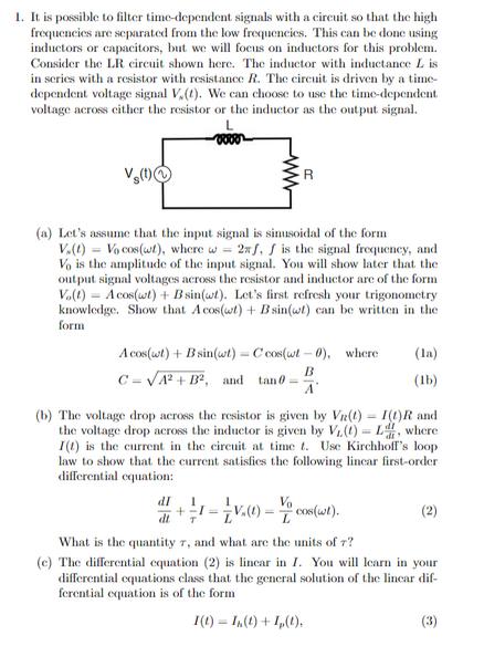
1. It is possible to filter time-dependent signals with a circuit so that the high frequencies are separated from the low frequencies. This can be done using inductors or capacitors, but we will focus on inductors for this problem. Consider the LR circuit shown here. The inductor with inductance L is in series with a resistor with resistance R. The circuit is driven by a time- dependent voltage signal V.(t). We can choose to use the time-dependent voltage across either the resistor or the inductor as the output signal. Vs(t) R (a) Let's assume that the input signal is sinusoidal of the form V.(t)= Vo cos(wt), where w = 2xf. f is the signal frequency, and Vo is the amplitude of the input signal. You will show later that the output signal voltages across the resistor and inductor are of the form Vo(t) Acos(wt) + B sin(wt). Let's first refresh your trigonometry knowledge. Show that Acos(wt) + Bsin(wt) can be written in the form Acos(wt) + B sin(wt)-C cos(wt-0), where B C=A+B, and tan A (la) (lb) (b) The voltage drop across the resistor is given by Vn(t) I(1) R and the voltage drop across the inductor is given by V(t)=L, where I(t) is the current in the circuit at time t. Use Kirchhoff's loop law to show that the current satisfies the following lincar first-order differential equation: dI 1 + 1 = V(1) - cons(wit). dt T (2) What is the quantity 7, and what are the units of 7? (e) The differential equation (2) is lincar in I. You will learn in your differential equations class that the general solution of the linear dif- ferential equation is of the form I(1) (t) + 1(t). (3) where I (t) is the most general solution to the homogeneous differ- ential equation dI dt T 1 +-I = 0, and I, (t) is any particular solution of the inhomogeneous differential equation (2). Show that In(t) Dexp(-t/T), (5) solves the homogeneous equation (4), where D is an arbitrary con- stant than can be chosen to give the correct initial current I(0). (d) Since the homogeneous solution (5) decays to zero for times t > T, at a long time after time t= 0 the solution to equation (2) will be given by just the particular solution Ip(t). Let's now focus on finding a particular solution by using the Aha! method. Show that Ip(t) Acos(wt) + B sin(wt), solves equation (2) if A and B are chosen correctly. The coefficients A and B have a simple form if they are written in terms of the dimen- sionless quantity wr, rather than w and 7 separately. The quantity WT tells you if the input frequency f is large or small compared to the natural response frequency of the circuit fo= 1/(2TT). If wr < < 1 then the input frequency f is small compared fo, and vice versa. (e) Choose the output signal from the time-dependent voltage across the resistor. Use your particular solution for I, (t) to determine the time- dependent voltage across the resistor Vr(t) = Ip(t)R. Use equation (1) to rewrite the voltage across the resistor in the form: Vr(t) = VRO cos(wt - 0), and find VRO in terms of Vo and wr. The response of a circuit is usually described in terms of the square of the ratio of the output amplitude to the input amplitude: (VRO/Vo)2. Show that the response is given by VRO Vo 1 1+ (WT) * (6) Show that the output amplitude is approximately equal the input amplitude at low frequencies, but small at high frequencies. Why is this called a low pass filter? (f) Now choose the output signal from the time-dependent voltage across the inductor. Use your particular solution for I, (t) to determine the voltage across the inductor V(t) = L. Use equation (1) to rewrite the voltage across the inductor in the form: VL(t) = VLO COS(wt - 0), and find VLO and the response function (VLO/Vo)2. Show that the response function is given by VLO Vo 2 = (WT) 1+ (WT)* Show that the output amplitude is approximately equal the input amplitude at high frequencies, but small at low frequencies. Why is this called a high pass filter? (g) Describe in words the two output signals that would result if the input signal was the sum of a wide range of frequencies? How might frequency filters be useful in electronic circuits?
Step by Step Solution
3.38 Rating (145 Votes )
There are 3 Steps involved in it
4 PT Put AB A ces et B sin est c cos ot0 A c cose cco c an0 c cos 0 tsin 0 c JAB I L moo... View full answer

Get step-by-step solutions from verified subject matter experts