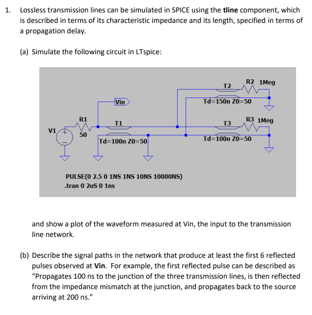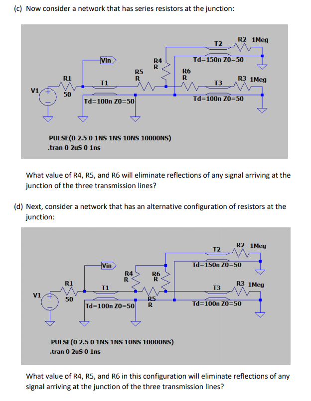

1. Lossless transmission lines can be simulated in SPICE using the tline component, which is described in terms of its characteristic impedance and its length, specified in terms of a propagation delay. (a) Simulate the following circuit in LTspice: 12 R2 iMeg Td=150n 20=501 13R3 1Meg V1 V 50 Td=100n Z0=50 Td=100n Zo=50 PULSE(0 2.5 0 1NS INS 10NS 10000NS) .tran 0 2uS 0 Ins and show a plot of the waveform measured at Vin, the input to the transmission line network. (b) Describe the signal paths in the network that produce at least the first 6 reflected pulses observed at Vin. For example, the first reflected pulse can be described as "Propagates 100 ns to the junction of the three transmission lines, is then reflected from the impedance mismatch at the junction, and propagates back to the source arriving at 200 ns." (c) Now consider a network that has series resistors at the junction: 12 R21Meg Td=150n 20=50 Vin R4 R5 RS R5 R6 R3 1Meg 50 d=100n ZO= Td=100n Z0=50 PULSE(O 2.5 0 1NS INS 10NS 10000NS) .tran 0 2uS o ins What value of R4, R5, and R6 will eliminate reflections of any signal arriving at the junction of the three transmission lines? (d) Next, consider a network that has an alternative configuration of resistors at the junction: R2 Meg Td=150n ZO=50 T R3 1 Meg I1M vi Td=100n Z0=50 R Td=100n Zo=50 PULSE(0 2.5 0 1NS INS 10NS 10000NS) .tran 0 2uS o Ins What value of R4, R5, and R6 in this configuration will eliminate reflections of any signal arriving at the junction of the three transmission lines? 1. Lossless transmission lines can be simulated in SPICE using the tline component, which is described in terms of its characteristic impedance and its length, specified in terms of a propagation delay. (a) Simulate the following circuit in LTspice: 12 R2 iMeg Td=150n 20=501 13R3 1Meg V1 V 50 Td=100n Z0=50 Td=100n Zo=50 PULSE(0 2.5 0 1NS INS 10NS 10000NS) .tran 0 2uS 0 Ins and show a plot of the waveform measured at Vin, the input to the transmission line network. (b) Describe the signal paths in the network that produce at least the first 6 reflected pulses observed at Vin. For example, the first reflected pulse can be described as "Propagates 100 ns to the junction of the three transmission lines, is then reflected from the impedance mismatch at the junction, and propagates back to the source arriving at 200 ns." (c) Now consider a network that has series resistors at the junction: 12 R21Meg Td=150n 20=50 Vin R4 R5 RS R5 R6 R3 1Meg 50 d=100n ZO= Td=100n Z0=50 PULSE(O 2.5 0 1NS INS 10NS 10000NS) .tran 0 2uS o ins What value of R4, R5, and R6 will eliminate reflections of any signal arriving at the junction of the three transmission lines? (d) Next, consider a network that has an alternative configuration of resistors at the junction: R2 Meg Td=150n ZO=50 T R3 1 Meg I1M vi Td=100n Z0=50 R Td=100n Zo=50 PULSE(0 2.5 0 1NS INS 10NS 10000NS) .tran 0 2uS o Ins What value of R4, R5, and R6 in this configuration will eliminate reflections of any signal arriving at the junction of the three transmission lines


