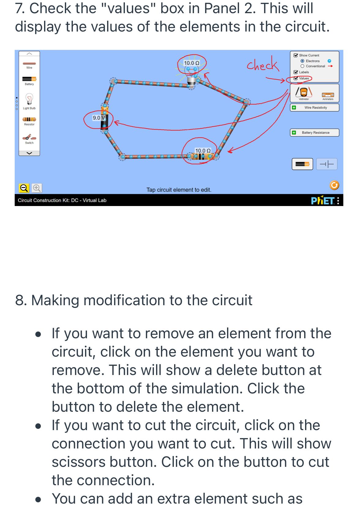
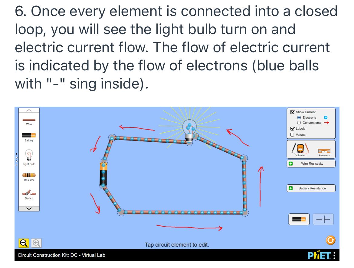
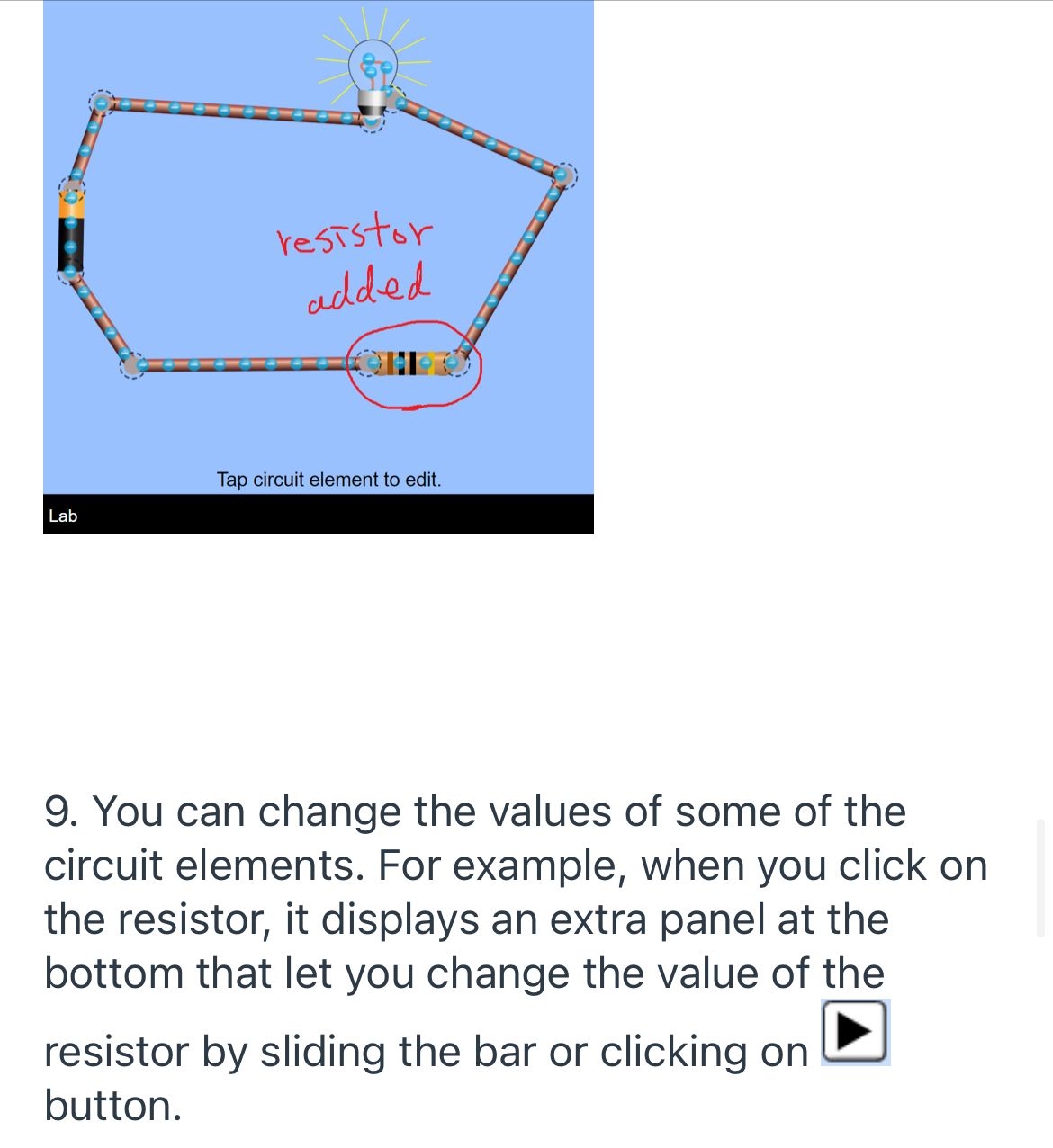
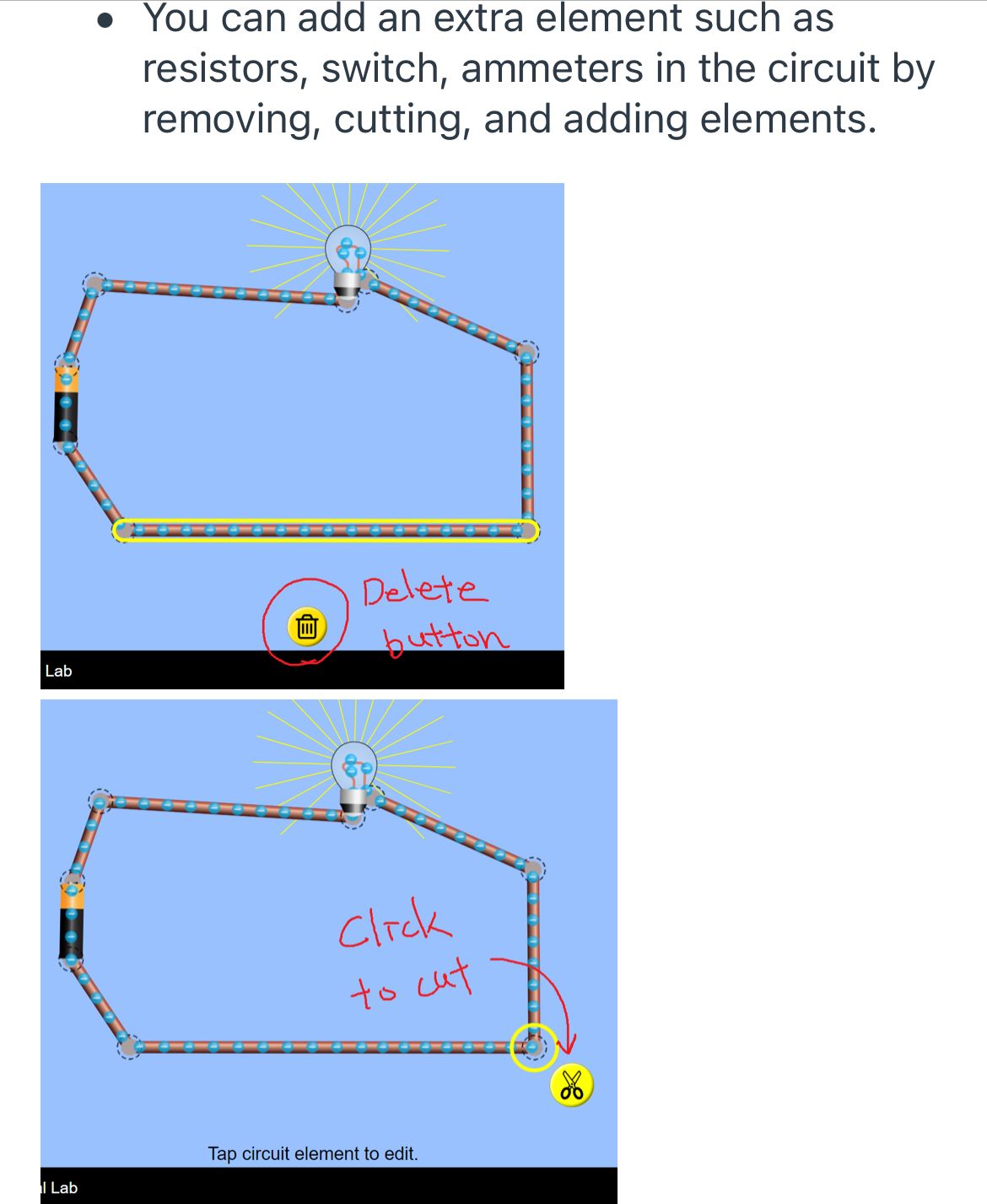
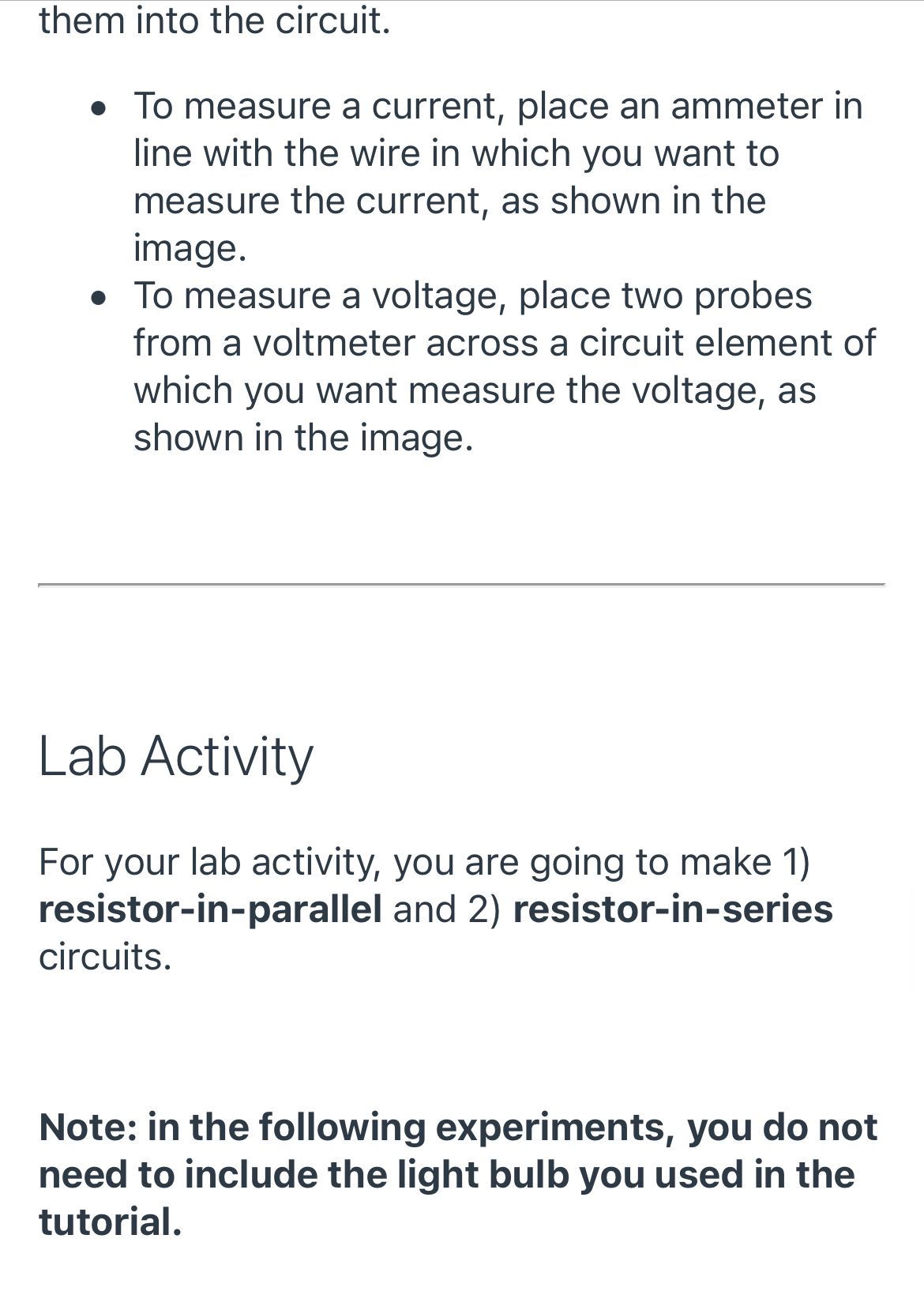
1. Open https://phet.colorado.edu/sims/html/circuit- construction-kit-dc-virtual-lab/latest/circuit- construction-kit-dc-virtual-lab_en.html from PhET. 2. It opens the following simulation. Show Current Electrons Wire B Conventional Labels O Values Battery Circuit Voltmeter
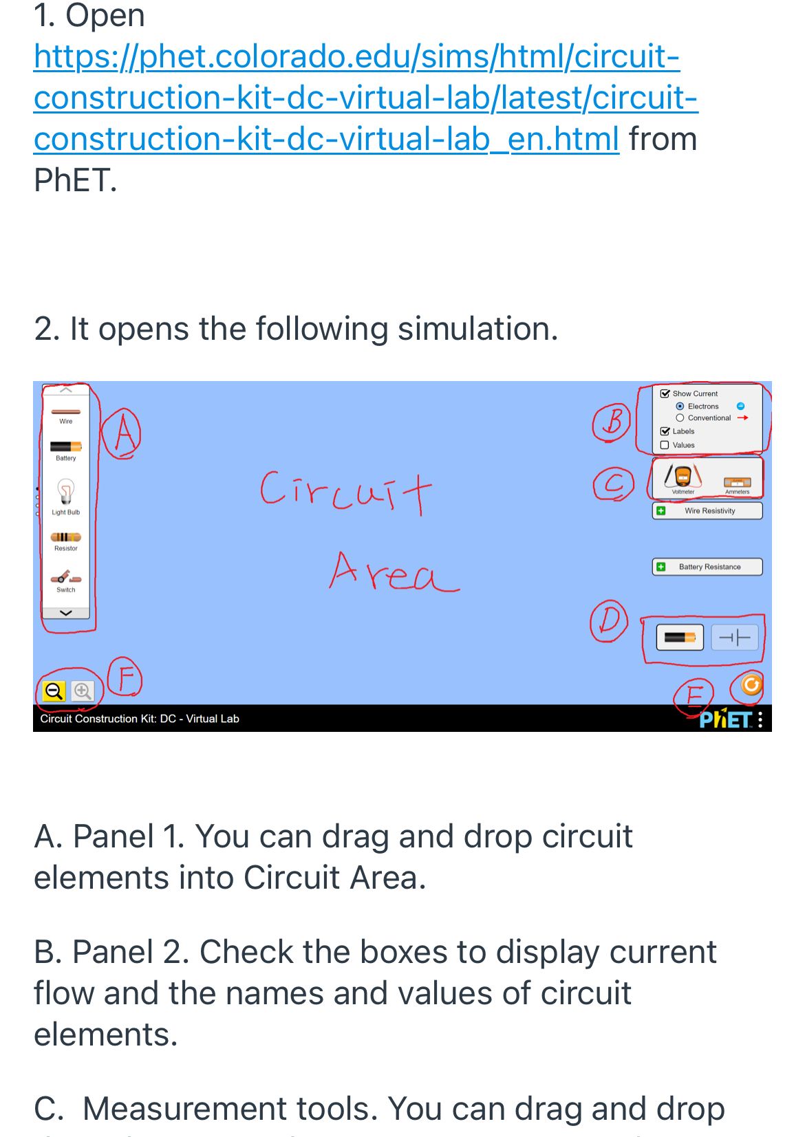
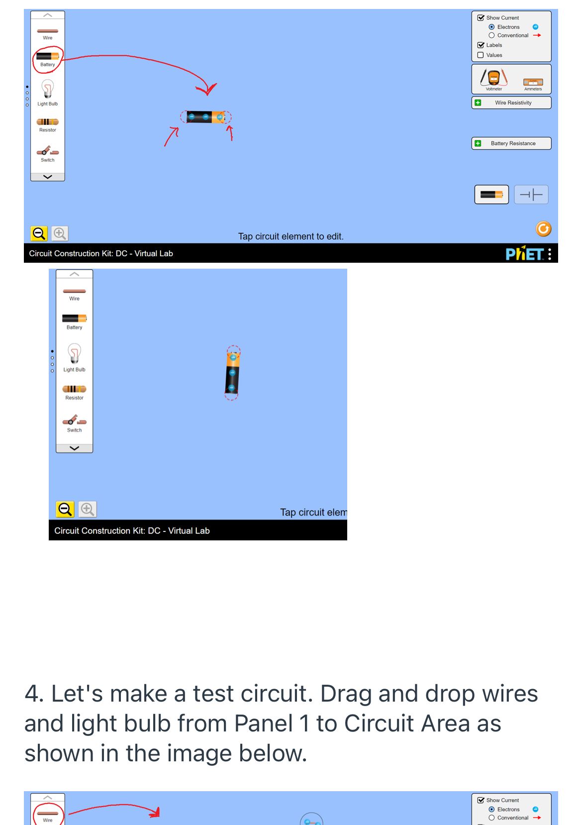
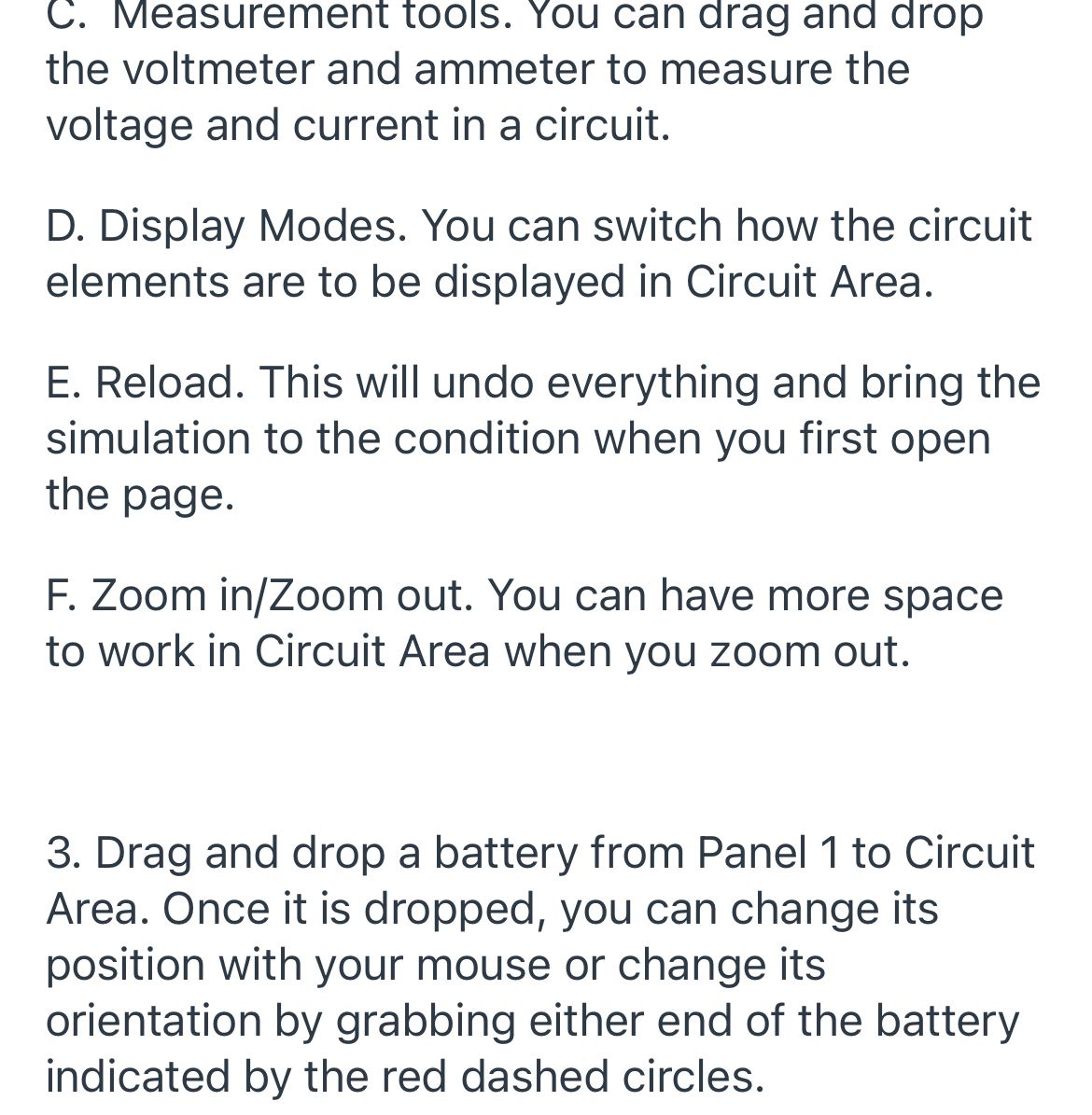
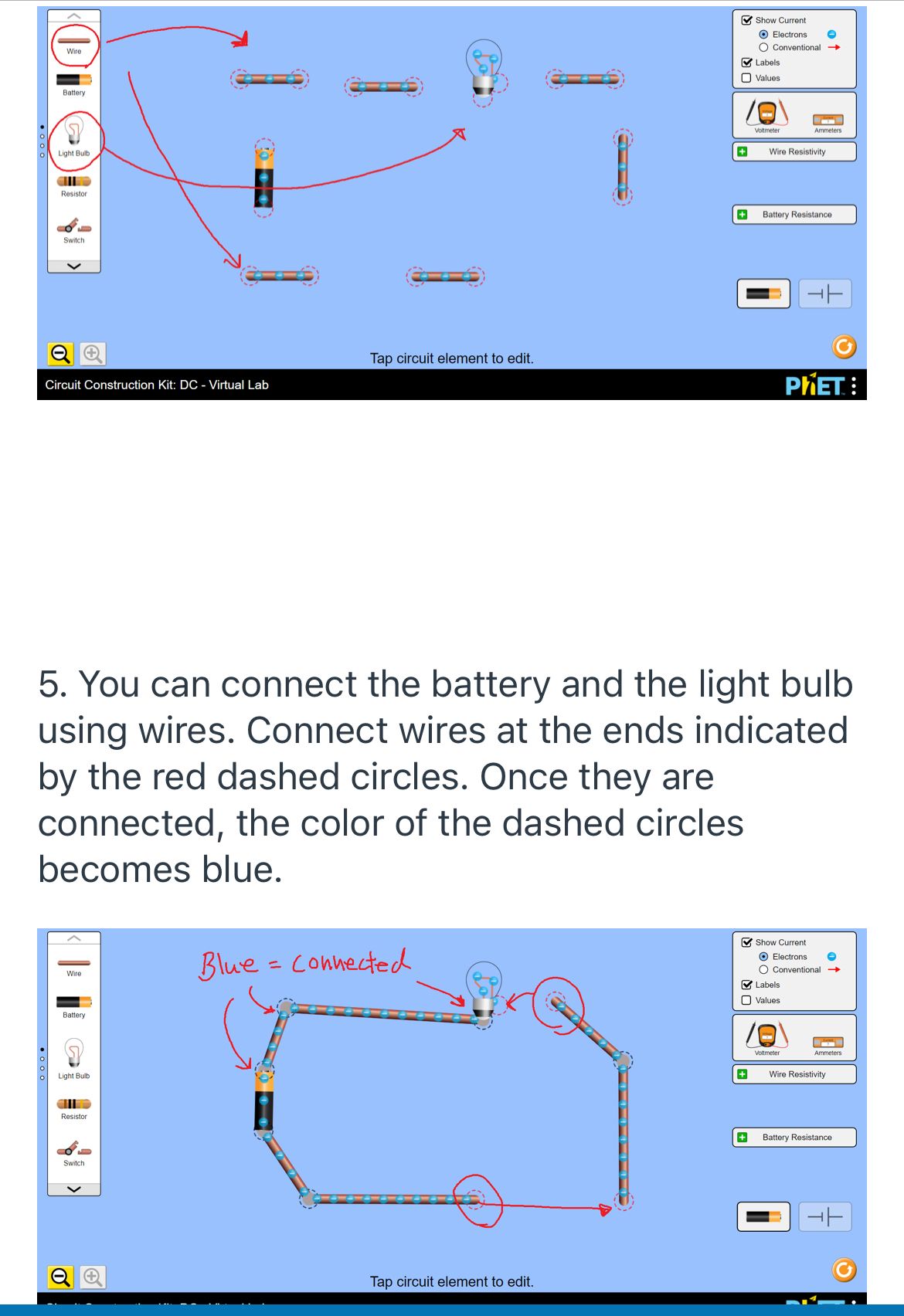
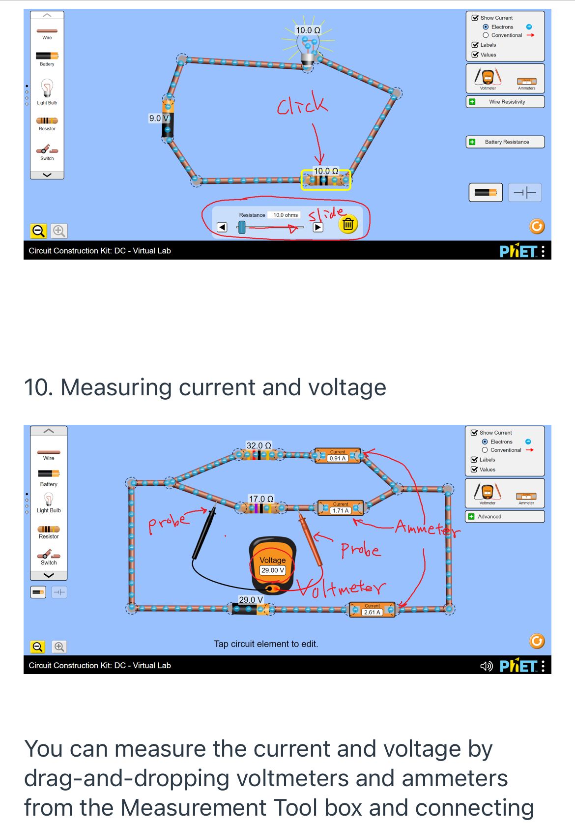
1. Open https://phet.colorado.edu/sims/html/circuit- construction-kit-dc-virtual-lab/latest/circuit- construction-kit-dc-virtual-lab_en.html from PhET. 2. It opens the following simulation. Show Current Electrons Wire B Conventional Labels O Values Battery Circuit Voltmeter Ammeters Light Built Wire Resistivity Resistor Area Battery Resistance Switch Circuit Construction Kit: DC - Virtual Lab PHET : A. Panel 1. You can drag and drop circuit elements into Circuit Area. B. Panel 2. Check the boxes to display current flow and the names and values of circuit elements. C. Measurement tools. You can drag and dropShow Current Electrons Wire Conventional Labels Values Battery Voltmeter Ammeters Light Built Wire Resistivity Resistor Resistance Switch Tap circuit element to edit. Circuit Construction Kit: DC - Virtual Lab PHET : Wire Battery Light Bulb Resistor Switch Tap circuit elem Circuit Construction Kit: DC - Virtual Lab 4. Let's make a test circuit. Drag and drop wires and light bulb from Panel 1 to Circuit Area as shown in the image below. Show Current Electrons ConventionalC. Measurement t00Is. You can drag and drop the voltmeter and ammeter to measure the voltage and current in a circuit. D. Display Modes. You can switch how the circuit elements are to be displayed in Circuit Area. E. Reload. This will undo everything and bring the simulation to the condition when you first open the page. F. Zoom in/Zoom out. You can have more space to work in Circuit Area when you zoom out. 3. Drag and drop a battery from Panel 1 to Circuit Area. Once it is dropped, you can change its position with your mouse or change its orientation by grabbing either end of the battery indicated by the red dashed circles. Show Current Electrons Wire Conventional - Labels Values Battery Voltmeter Light Bulb + Wire Resistivity Resistor Battery Resistance Switch -+- Tap circuit element to edit. Circuit Construction Kit: DC - Virtual Lab PRET : 5. You can connect the battery and the light bulb using wires. Connect wires at the ends indicated by the red dashed circles. Once they are connected, the color of the dashed circles becomes blue. Show Current Wife Blue = connected Electrons Conventional Labels Values Battery Voltmeter ummmeters Light Bull + Wire Resistivity Resistor Battery Resistance Switch Tap circuit element to edit.7. Check the "values" box in Panel 2. This will display the values of the elements in the circuit. 8. Making modification to the circuit 0 If you want to remove an element from the circuit, click on the element you want to remove. This will show a delete button at the bottom of the simulation. Click the button to delete the element. . If you want to cut the circuit, click on the connection you want to cut. This will show scissors button. Click on the button to cut the connection. 0 You can add an extra element such as 6. Once every element is connected into a closed loop, you will see the light bulb turn on and electric current flow. The flow of electric current is indicated by the flow of electrons (blue balls wit "-" sing inside). 9. You can change the values of some of the circuit elements. For example, when you click on the resistor it displays an extra panel at the bottom that let you change the value of the resistor by sliding the bar or clicking on B button. 0 You can add an extra element such as resistors, switch, ammeters in the circuit by removing, cutting, and adding elements. them into the circuit. 0 To measure a current, place an ammeter in line with the wire in which you want to measure the current, as shown in the image. . To measure a voltage, place two probes from a voltmeter across a circuit element of which you want measure the voltage, as shown in the image. Lab Activity For your lab activity, you are going to make 1) resistor-in-parallel and 2) resistor-in-series circuits. Note: in the following experiments, you do not need to include the light bulb you used in the tutorial. Show Current 10.0 0 Electrons Wire Conventional Labels Values Battery ofmeter Light But click Wire Resistivity 9.0 V Resistor Battery Resistance Switch -10.0 0 Resistance 10.0 ohms slide Circuit Construction Kit: DC - Virtual Lab PHET : 10. Measuring current and voltage Show Current 32.0 0 Electrons Conventional Wire Labels Values Battery 17.0 0 Voltmeter Ammeter Light Bulb 1.71A probe + Advanced Resistor Ammeter Probe Switch Voltage 29.00 V Voltmeter 29.0 V 2.61 A Tap circuit element to edit. Circuit Construction Kit: DC - Virtual Lab 4) PHET : You can measure the current and voltage by drag-and-dropping voltmeters and ammeters from the Measurement Tool box and connectingor decreases? How is the current split into three resistors? Split equally or one resistor has more current passing through than the others? Voltages across the resistors increase, remain the same, or decrease? Experiment 2 series circuit 1. Build an electric circuit with one battery and three 500 resistors. The three resistors should be placed in series. 2. Set the voltage on the battery to 50 V. 3. Measure and record the following: - Total current in the circuit - Current through each resistor - Voltage across each resistor 4. Take a screenshot of the simulation (this should include the voltmeter(s) and ammeter(s)) 5. Change the resistance of only one of the Experiment 1 Parallel Circuit 1. Build an electric circuit with one battery and three 500 resistors. The three resistors should be placed parallel to each other. 2. Set the voltage on the battery to 50 V. 3. Measure and record the following: - Total current in the circuit - Current through each resistor - Voltage across each resistor 4. Take a screenshot of the simulation (this should include the voltmeter(s) and ammeter(s)) 5. Change the resistance of only one of the three resistors to 100 Q, and repeat the step 3 and 4 above. 6. Compare the two measurements (three 50 0 vs. two 50 Q and one 100 Q) and describe and explain what you observed. Total current increases, remains the same, For each experiment above, submit the following: 0 Two screenshots (one from three 50 0 case, the other from two 50 Q and one 100 0 case) 0 Measured values of total current, current through each resistor, and voltage across each resistor 0 Discussion on the comparison of two measurements (i.e., three 50 Q vs. two 50 Q and one 100 Q) three resistors to 100 Q, and repeat the step 3 and 4 above. 6. Compare the two measurements (three 50 0 vs. two 50 Q and one 100 Q) and describe and explain what you observed. Total current increases, remains the same, or decreases? Are the currents the same or different in the three resistors? How is the voltages across the three resistors split
Step by Step Solution
There are 3 Steps involved in it
Step: 1
Get Instant Access to Expert-Tailored Solutions
See step-by-step solutions with expert insights and AI powered tools for academic success
Step: 2
Step: 3
Ace Your Homework with AI
Get the answers you need in no time with our AI-driven, step-by-step assistance