

Answered step by step
Verified Expert Solution
Question
1 Approved Answer
1. Problem 10.1(I already done this) 10.1 represent the following decimal numbers in both sign magnitude and 2's complement using 16bits: +512, -29 Answer: +512
1. Problem 10.1(I already done this) 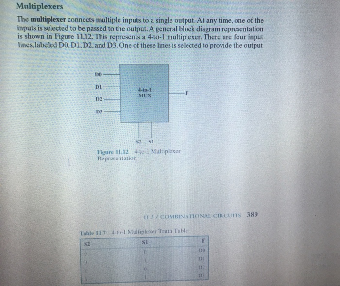
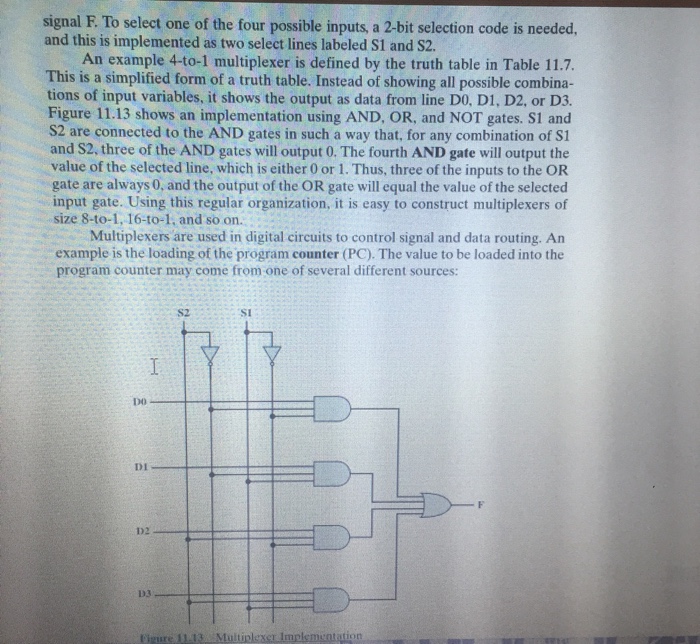
Multiplexers The multiplexer connects multiple inputs to a single output. At any time, one of the inputs is selected to be passed to the output.A general block diagram representation is shown in Figure 11.12. This represents a 4-to-1 multiplexer. There are four input lines, labeled DO. D1. D2, and D3. One of these lines is selected to provide the output DO DI D2 D3 4-t0-1 MUX S2 S1 Figure 11.12 4to-1 Multiplexer Representation 113 / COMBINATIONAL CIRCUITS 389 Table 11.7 4 to-1 Multuplexer Truth Table S2 s1 Do D1 D2 Multiplexers The multiplexer connects multiple inputs to a single output. At any time, one of the inputs is selected to be passed to the output.A general block diagram representation is shown in Figure 11.12. This represents a 4-to-1 multiplexer. There are four input lines, labeled DO. D1. D2, and D3. One of these lines is selected to provide the output DO DI D2 D3 4-t0-1 MUX S2 S1 Figure 11.12 4to-1 Multiplexer Representation 113 / COMBINATIONAL CIRCUITS 389 Table 11.7 4 to-1 Multuplexer Truth Table S2 s1 Do D1 D2 10.1 represent the following decimal numbers in both sign magnitude and 2's complement using 16bits: +512, -29
Answer: +512 ( sign magnitude:0000 0010 0000 0000; 2's complement: 0000 0010 0000 0000)
-29 ( sign magnitude:0000 0000 0001 1101; 2's complement: 1111 1111 1110 0011)
PLEASE DO THE Question BELOW !!!!!!!!! Thx
2. Implement the half adder with two 4-to-1 multiplexers (similar to figure 11.12 )
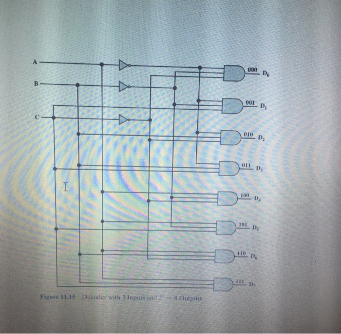
2. Implement the full adder with one 3-to-3 decoder (similar to figure 11.15) and a few additional gates.
3.you are asked scratch(i.e. Without using full adders!) one circuit that would add two 2-bit binary numbers the circuit should accept four inputs A1,A0, and B1,B0, and produce three outputs C1 and S1,S0. Follow the standard design produre and show .
(I) the truth table for the entire circuit
(II)the simplification using karnaugh maps
(III)the circuit diagram show the screen capture from Logic Works showing the circuit diagram for the entire 2-bit adder.
For implementation use only inverters (NOT gates) and (NAND gates) each with only two inputs (like 7400)
Step by Step Solution
There are 3 Steps involved in it
Step: 1

Get Instant Access to Expert-Tailored Solutions
See step-by-step solutions with expert insights and AI powered tools for academic success
Step: 2

Step: 3
Ace Your Homework with AI
Get the answers you need in no time with our AI-driven, step-by-step assistance
Get Started
Databases Theory And Applications 33rd Australasian Database Conference Adc 2022 Sydney Nsw Australia September 2 4 2022 Proceedings Lncs 13459
Authors: Wen Hua ,Hua Wang ,Lei Li
1st Edition
3031155114, 978-3031155116